
Universal mounting block system

a mounting block and universal technology, applied in the direction of lighting and heating apparatus, coupling device connection, heating type, etc., can solve the problems of affecting the installation of the wall, so as to avoid the loss of critical parts, facilitate installation, and easy adjustment

Active Publication Date: 2012-04-10
WESTLAKE ROYAL BUILDING PROD INC
View PDF6 Cites 9 Cited by
  • Summary
  • Abstract
  • Description
  • Claims
  • Application Information

AI Technical Summary

Benefits of technology

The system simplifies installation, prevents part loss, ensures secure and water-resistant connections, and accommodates various fixture sizes and configurations, enhancing structural strength and versatility on different wall materials.

Problems solved by technology

Normally, heavy-duty fiberboard or plywood is not used throughout a frame construction due to the cost.
In many cases, neither the siding nor the underlying sheathing is separately capable of supporting a fixture to be mounted on the exterior wall.
This is especially important when apertures must be formed in both the substrate and the siding to accommodate a fixture, but which weakens the wall.
However, using conventional mounting blocks, this process has not always been easy to carry out.
Consequently, the process can be extremely awkward, especially if unskilled labor is employed, or adverse conditions ensue.
Another problem, even for highly skilled workers, is the fact that conventional mounting blocks normally come in three separate pieces, often with separate connecting devices for each piece.
Under the often-chaotic conditions of construction sites, pieces of the mounting blocks, especially the connectors, can be misplaced or lost.
This results in delays or other difficulties, and often leads to the expedient of ordering redundant mounting blocks just to make certain that a full kit is available when needed.
However, there have been difficulties with such arrangements since sometimes the attached components must be separated for one to be mounted, and then reattached to each other.
This often leads to breakage.
Otherwise, it would be very difficult to position and connect the holding piece to the wall using conventional mounting blocks.
Unfortunately, this upper holding piece can be lost.
In some cases, even if the upper holding piece is not lost, its connectors can be, thereby compromising the overall mounting block.
However, as is so often the case on a construction site, abuse can occur and the hinges can break.
Likewise, the connections between the rotating holding pieces and the rest of the mounting block can also be broken, creating a separation that might be very difficult to repair.
Even if repair is possible, there is the possibility of water working its way past the water tight seals of the mounting block and into the vulnerable, underlying wall.
There are other drawbacks to this design.
Further, the rotation of the holding pieced does not permit an optimum fit for locking purposes, even though some variation of siding thicknesses can be accommodated for this particular design.
As with any plastic design, general warping of the overall structure of the mounting block may lead to the intrusion of water at various points through and around the mounting block.
Also, as is the case at any construction site, less than precise measurements may result in situations that cannot be accommodated by a particular mounting block.
This would result in a questionable connection the mounting block and the building, compromising both the fixture and the surrounding siding.
Another major drawback of the conventional mounting block art is that a wide range of different fixtures must be accommodated.
On large construction sites with substantial numbers of different mounting blocks, the complexity associated with multiple installations of different types of blocks can become so great as to be debilitating.
A further drawback with much of the conventional mounting block art is that very often substantial numbers of parts are involved in the mounting of each fixture (for example: fixture, decorative cover plate, mounting block base, electrical box, siding flange and / or multiple cover plates for the electrical box and mounting block).
These multiple parts require multiple connections to each other so that there is very often a chain of connections, some of which may not be particularly secure.
As a result, even if the installation takes places properly, the overall assembly may not be particularly secure.
This can be both expensive and dangerous with electrical fixtures.

Method used


Image

  • Universal mounting block system
  • Universal mounting block system
  • Universal mounting block system

Examples


Embodiment Construction

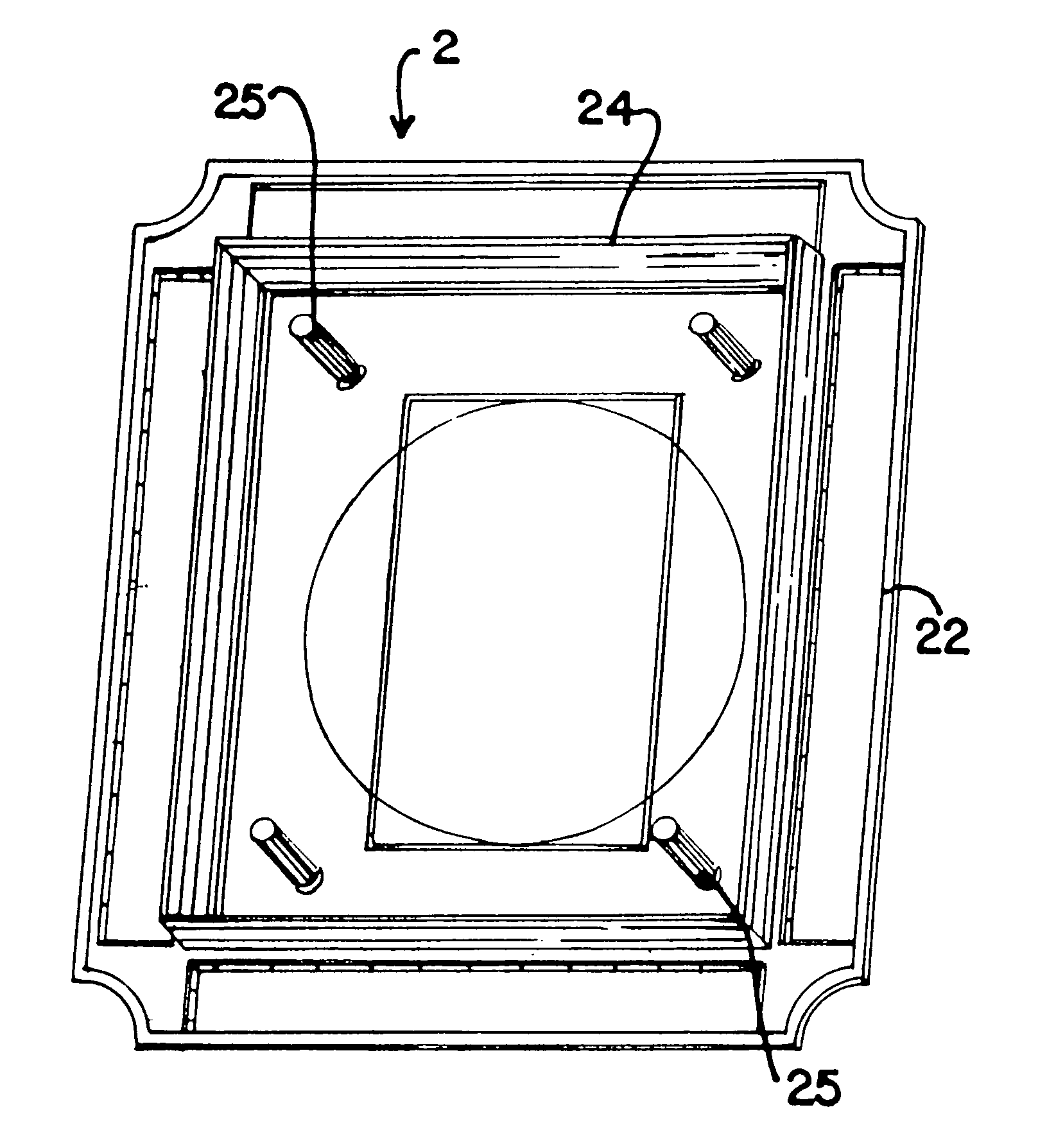
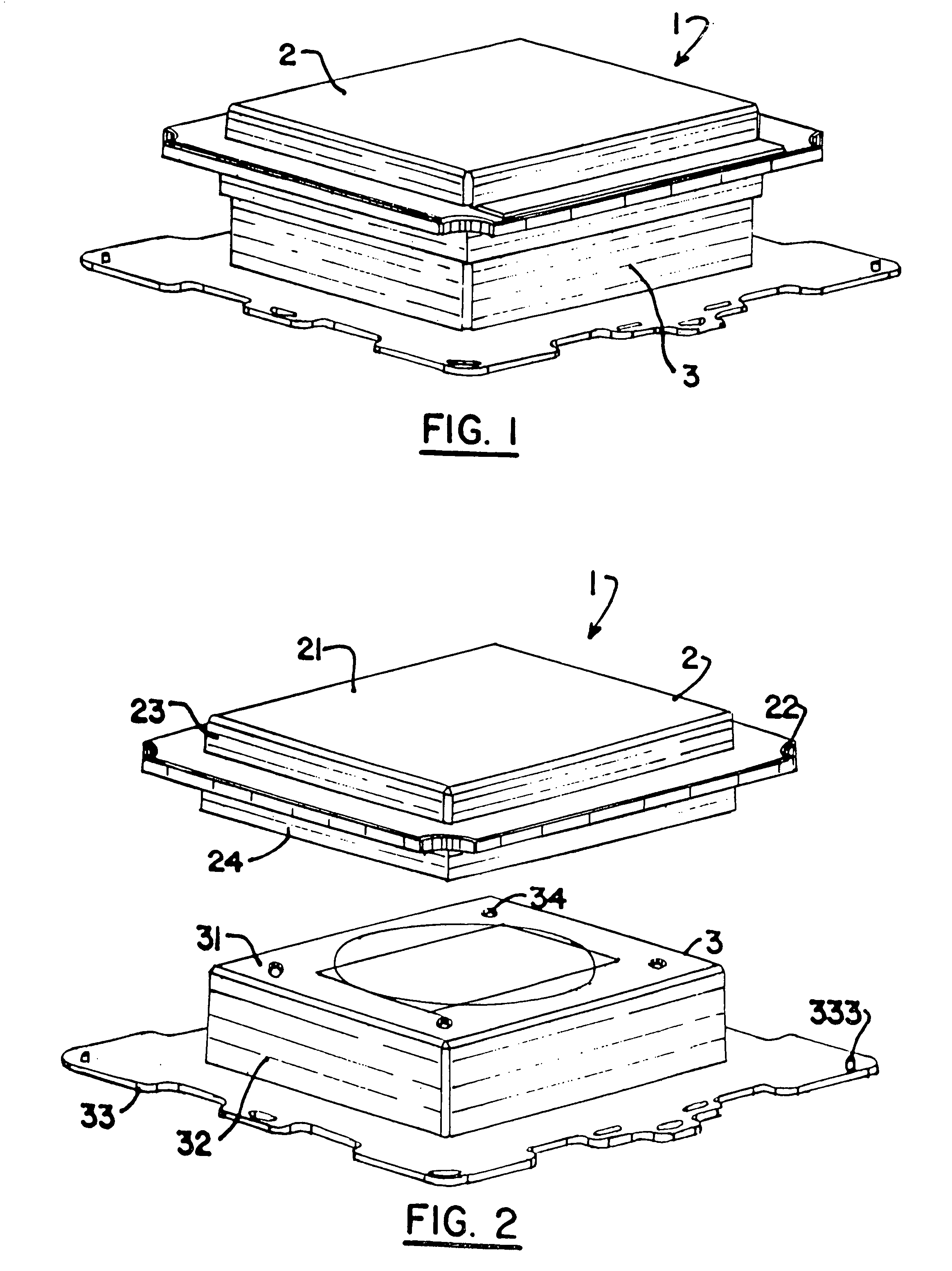
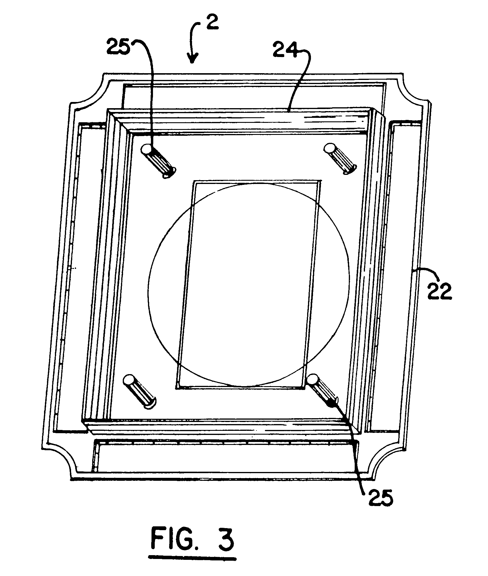
[0049]The universal wall-mounting block system 1 of the present invention is depicted in FIGS. 1-4, it its most basic form. The wall-mounting block system of the present invention is meant in a first preferred embodiment to be mounted around an aperture in a wooden frame wall of standard construction (with siding). However, the aperture is not necessary for the proper operation of the present invention, which can be mounted around a fixture such as a water spigot. It is the fixture that dictates the characteristics of the aperture, and some of the characteristics of the mounting block system 1.

[0050]One strength of the universal wall-mounting block 1 of the present invention is that it is effective even on walls constituted by flimsy materials. The present invention facilitates use with (or without) an aperture in almost any type of structural material. This can include anything from plastic foam to steel. Preferably the wall structure will have some sort of siding to help facilitat...


PUM


Abstract

A wall-mounting block or frame is used to mount fixtures to exterior building walls having siding. The wall-mounting block includes two major parts, a first or base section and a second or holding section which are both configured as cap-like structures detachably connected to each other with integrated, adjustable connectors. The present design eliminates the need for special hardware to attach the holding section to the base section, and helps prevent awkward mounting situations.

Description

RELATED APPLICATIONS[0001]This is a: CONTINUATION-IN-PART of U.S. patent application Ser. No. 11 / 482,521, filed: Jul. 7, 2006 which is a Continuation-In-Part based on U.S. Utility patent application Ser. No. 10 / 435,258, filed: May 9, 2003 now U.S. Pat. No. 7,510,153FIELD OF THE INVENTION[0002]The present invention is generally related to frames, blocks, brackets, or other structures for mounting fixtures to a wall. More particularly, the present invention is directed to a wall-mounting block that accommodates a wide variety of fixture types and sizes while easily locking over the siding of an exterior wall on which the mounting block is used.BACKGROUND ART[0003]Standard frame construction is used in virtually all residential and related construction in the United States, and in many other places throughout the world. This method of construction includes a wooden or steel framework of studs covered with a light sheathing of foam, light fiberboard or plywood, Celotex™, or any number o...

Claims


Application Information

Patent Timeline
Patent Type & Authority Patents(United States)
IPC IPC(8): H02G3/08B65D6/28H01R13/502
CPCF24F13/082
Inventor HENDRICKS, ROBERT
Owner WESTLAKE ROYAL BUILDING PROD INC
Learn More