
Device for interconnecting a first element and a second element as well as a pump comprising such a device

a technology of interconnection and device, which is applied in the direction of couplings, liquid fuel engines, rod connections, etc., can solve the problems of small slip between the interconnection of the impeller and the drive shaft will deteriorate, and the impeller and the socket will be difficult to adjust the mutual axial location of the elements, etc., to achieve the effect of increasing the frictional for

Active Publication Date: 2014-08-26
XYLEM IP HLDG
View PDF26 Cites 1 Cited by
  • Summary
  • Abstract
  • Description
  • Claims
  • Application Information

AI Technical Summary

Benefits of technology

This invention aims to improve interconnection devices by allowing better transmission of rotational motion between two elements, providing a better connection upon sudden jerks, and not requiring redesign of the elements. Additionally, the device has improved durability. The invention achieves this by having slits that run parallel to the device's longitudinal axis and intersect with a geometrical plane, creating a partially wedged relationship between the device's parts, which increases friction to improve the connection.

Problems solved by technology

Such a joint is often to a great extent appropriate but it is often difficult to release the elements from each other without damaging them, it is also difficult to adjust the mutual axial location of the elements.
However, high initial starting torque or other types of sudden jerks, which may occur especially when the pump operates in heavily polluted liquids, tend to cause a small slip between the impeller and the socket and / or between the drive shaft and the socket.
Consequently, the different elements will wear and the interconnection of the impeller and the drive shaft will deteriorate, the consequence being that the transmission of rotational motion may be lost.

Method used


Image

  • Device for interconnecting a first element and a second element as well as a pump comprising such a device
  • Device for interconnecting a first element and a second element as well as a pump comprising such a device
  • Device for interconnecting a first element and a second element as well as a pump comprising such a device

Examples


Embodiment Construction

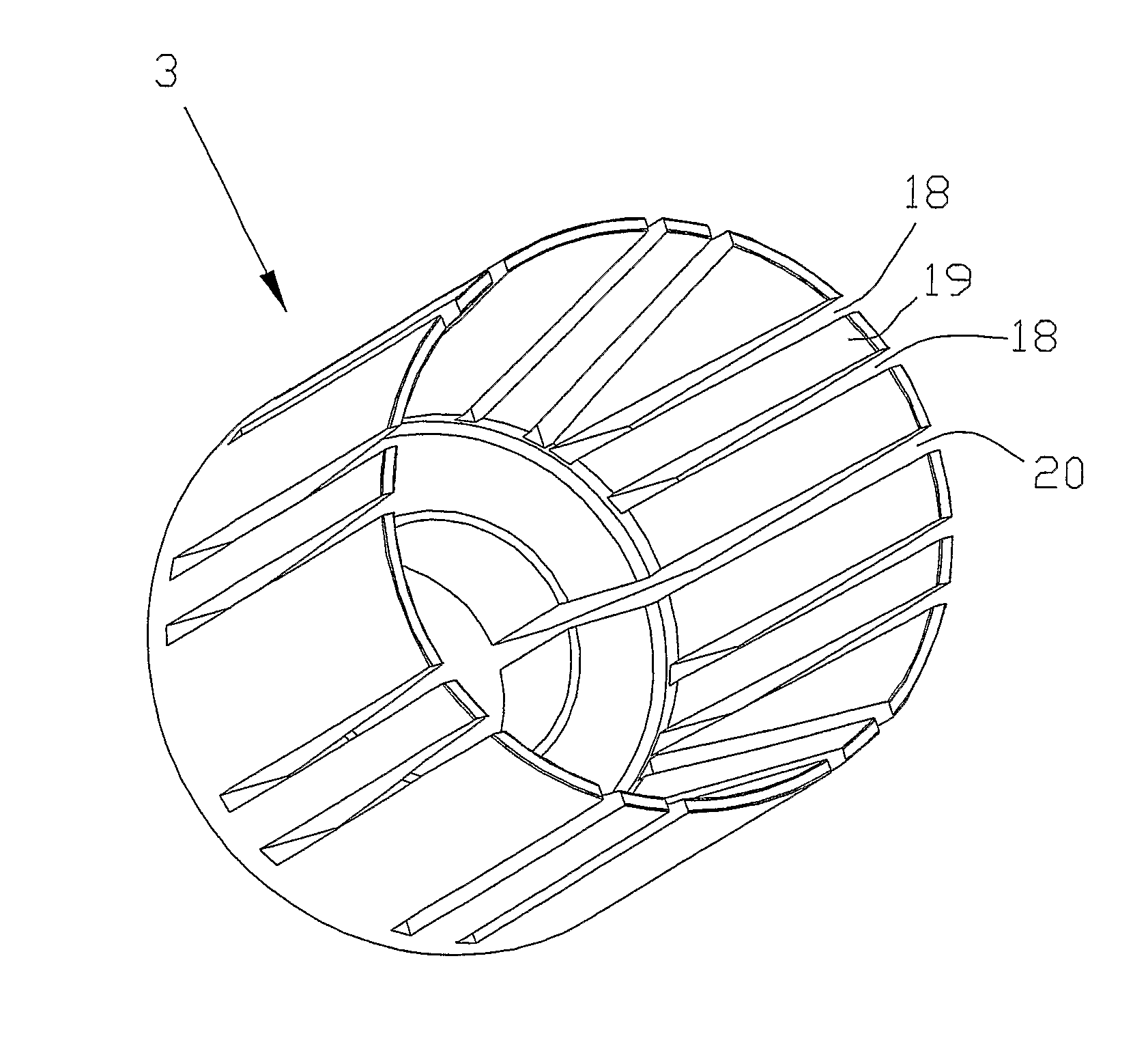
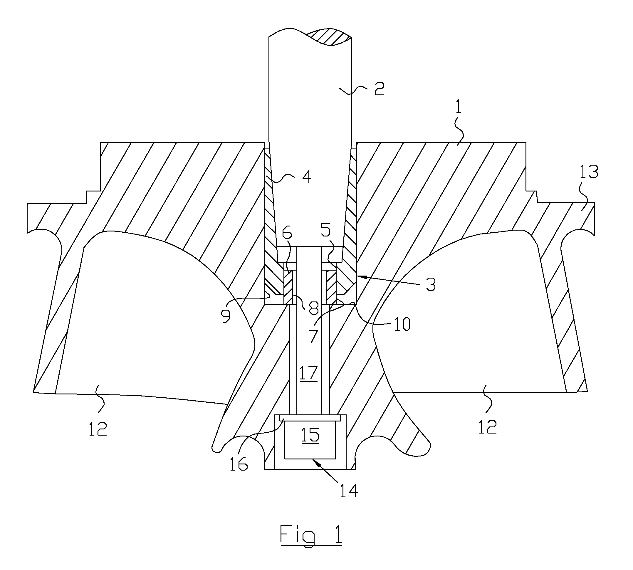
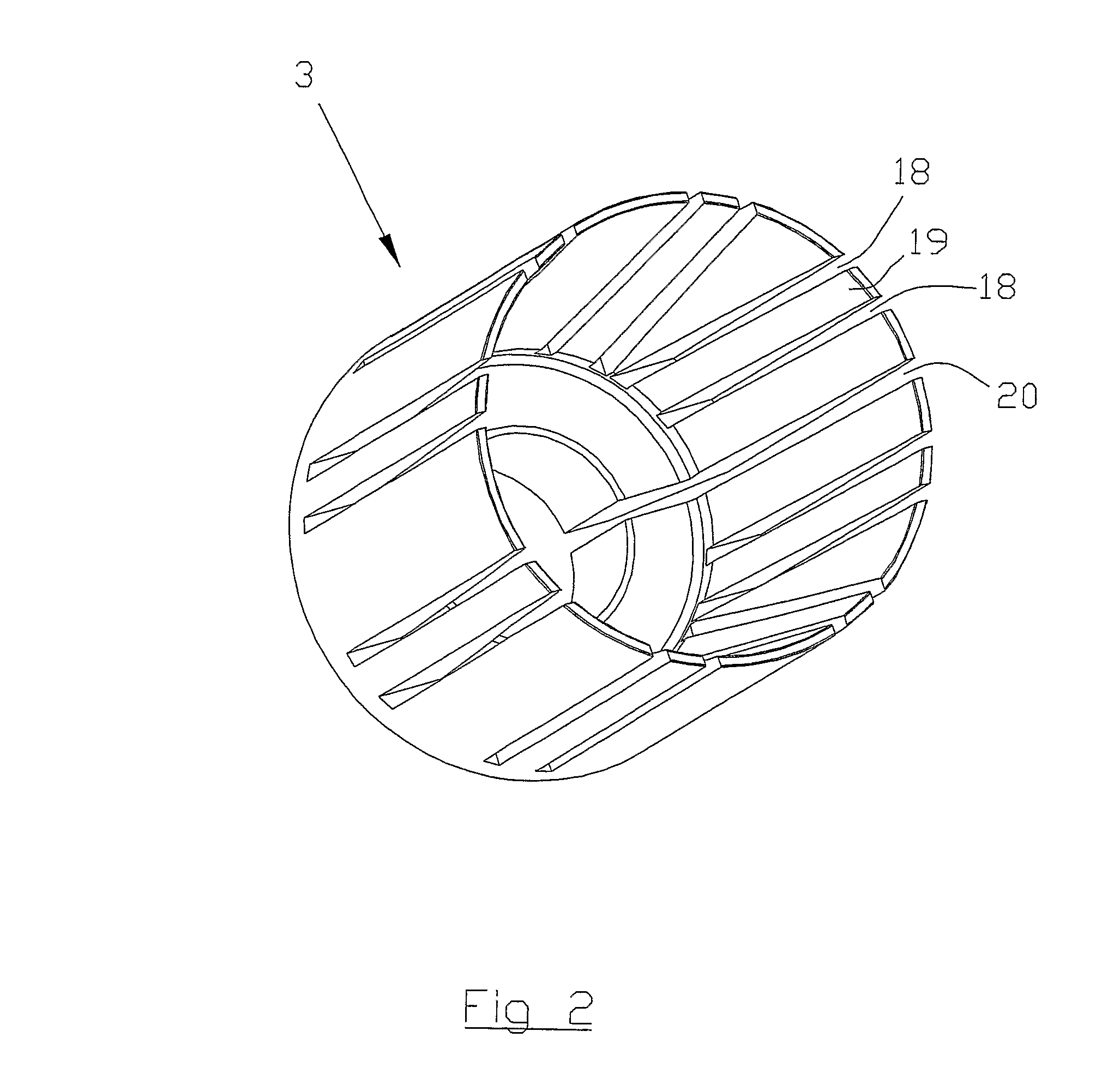
[0018]FIG. 1 shows a schematic cross sectional view of an impeller 1, a drive shaft 2, and a device 3, or socket, according to the invention, said device 3 being arranged between said impeller 1 and said drive shaft 2 in order to interconnect them to each other. Even thus the inventive device 3 has a broad applicability, i.e. to interconnect a first and a second element to each other in order to transmit a rotational motion, the device will be described arranged in a pump (not fully shown). The invention relates according to a second aspect to pumps in general, but in the described embodiment the pump is constituted by a submergible centrifugal pump. In FIG. 1 most parts of the pump are removed for the sake of simplicity of reading the figure.

[0019]The location of the impeller 1 in relation to an impeller seat (not shown) is of great importance for obtaining a suitable operating performance of the pump. When a pump pumps liquids containing solid matter, such as strongly abrasive par...


PUM


Abstract

In a first aspect the invention relates to a device for interconnecting a first element (2) and a second element (1) to each other in order to transmit a rotational motion. The device (3) comprises a tubular wall (4) having a circular inner surface, a part of which that is adjacent to said first end being arranged to abut said first element (2), and having a circular outer surface, a part of which that is adjacent to said first end being arranged to abut said second element (1). Furthermore, said tubular wall (4) comprises at least one pair of slits (18), which slits (18) are adjacent to each other and extends from said first end towards said second end, obtaining a finger shaped segment (19), which is deflectable in relation to neighboring parts of said tubular wall (4). The invention also relates to a pump comprising such a device (3).

Description

TECHNICAL FIELD OF THE INVENTION[0001]The present invention relates generally to the field of devices for interconnecting elements to each other in order to transmit a rotational motion, and more specifically to a device for a pump, which device is arranged to interconnect an impeller and a drive shaft. Further, the present invention relates specifically to the field of pumps for sewage or waste water. The device comprises an axial through hole that extends from a first end to a second end and generates a tubular wall having a circular inner surface, a part of which that is adjacent to said first end being arranged to abut said first element, and having a circular outer surface, a part of which that is adjacent to said first end being arranged to abut said second element. The invention also relates to a pump comprising such a device.BACKGROUND OF THE INVENTION[0002]Conventional pumps—specifically centrifugal or axial pumps—comprises a rotatable impeller mounted onto a drive shaft, w...

Claims


Application Information

Patent Timeline
Patent Type & Authority Patents(United States)
IPC IPC(8): F16B7/02
CPCY10T403/4637F16D1/097F04D29/20Y10T403/7069F16D1/09
Inventor HALLGREN, GERT
Owner XYLEM IP HLDG
Learn More