
Soft ventable relief valve

a venting relief valve and soft technology, applied in the direction of valve operating means/releasing devices, functional valve types, transportation and packaging, etc., can solve the problems of rapid increase in system pressure and flow, system shock wave generation, and low pressure setting determined, and achieve the effect of increasing the relief setting of the valve and low pressure setting

Inactive Publication Date: 2008-12-23
SUN HYDRAULICS LLC
View PDF9 Cites 19 Cited by
  • Summary
  • Abstract
  • Description
  • Claims
  • Application Information

AI Technical Summary

Benefits of technology

The present invention is a pilot-operated relief valve that limits the maximum pressure in a high-pressure hydraulic system and controls the rate of pressure rise. It includes a main section, a pilot section, and an operating pressure adjustment section. The valve has a hollow pilot piston that is hydraulically loaded to compress the pilot springs, which increase the relief setting of the valve. The pilot section allows the main piston to open immediately when pressure acting against the face of the main piston produces a force greater than the force exerted on the main piston by the main spring. The pilot sleeve will return to the original starting position against the adjustment section to minimize potential spikes in system pressure. The valve is designed to limit the rate of pressure rise and prevent excessive pressure spikes.

Problems solved by technology

Venting the valve in this way essentially short circuits the pilot section, resulting in a very low pressure setting determined by the bias pressure of the main section.
With typical relief valves, rapid increases in system pressure and flow can generate a shock wave in the system, ultimately absorbed by components, hoses, or fittings.

Method used


Image

  • Soft ventable relief valve
  • Soft ventable relief valve
  • Soft ventable relief valve

Examples


example 1

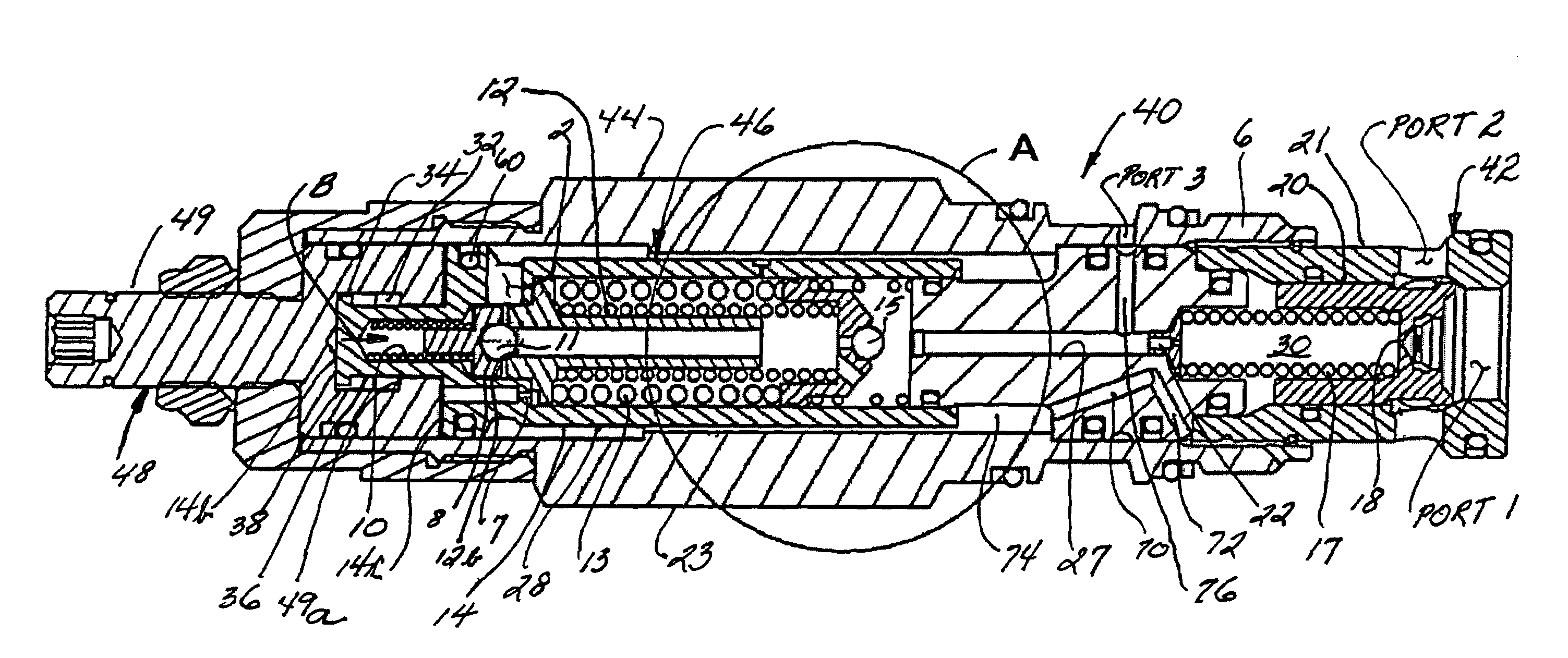
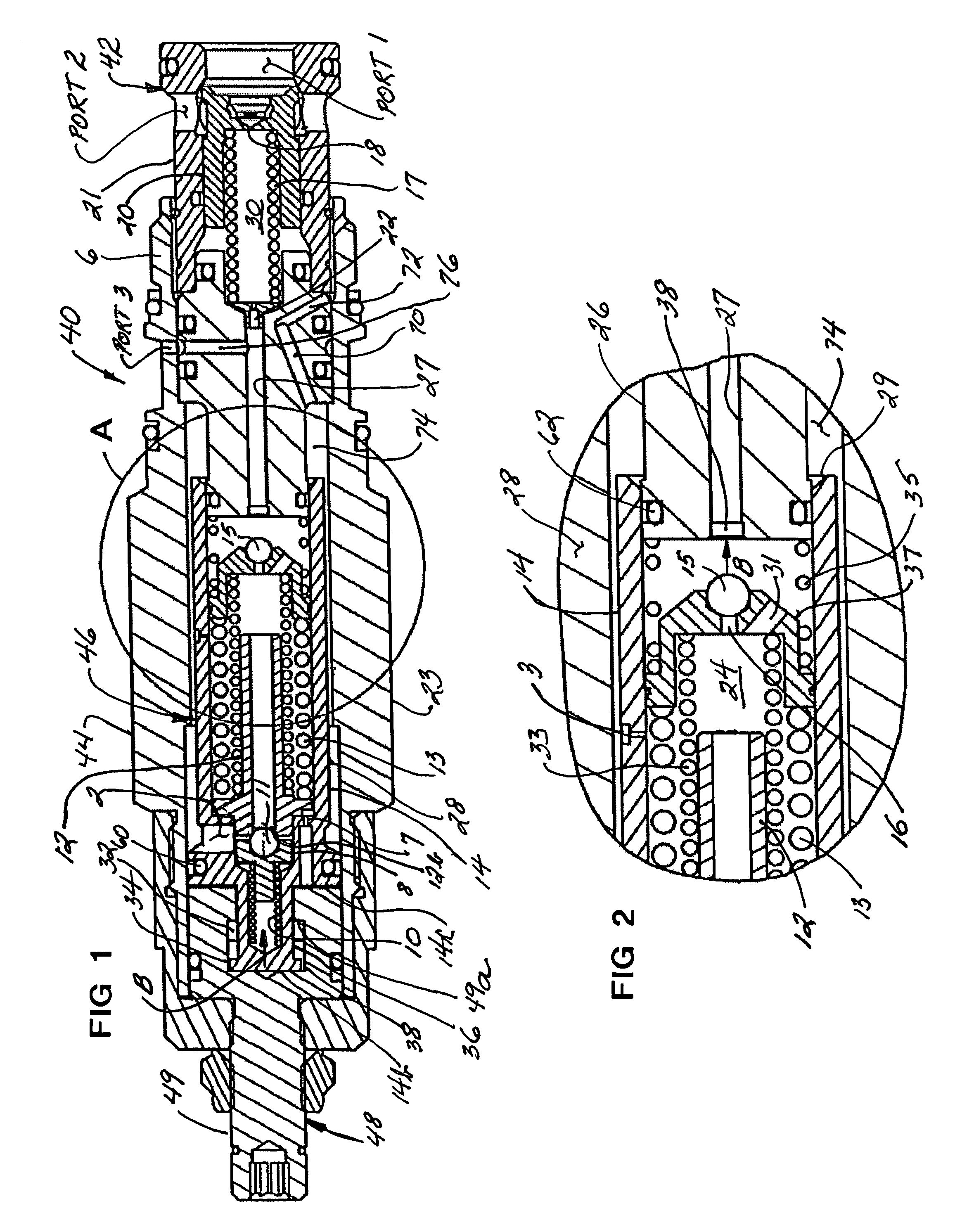
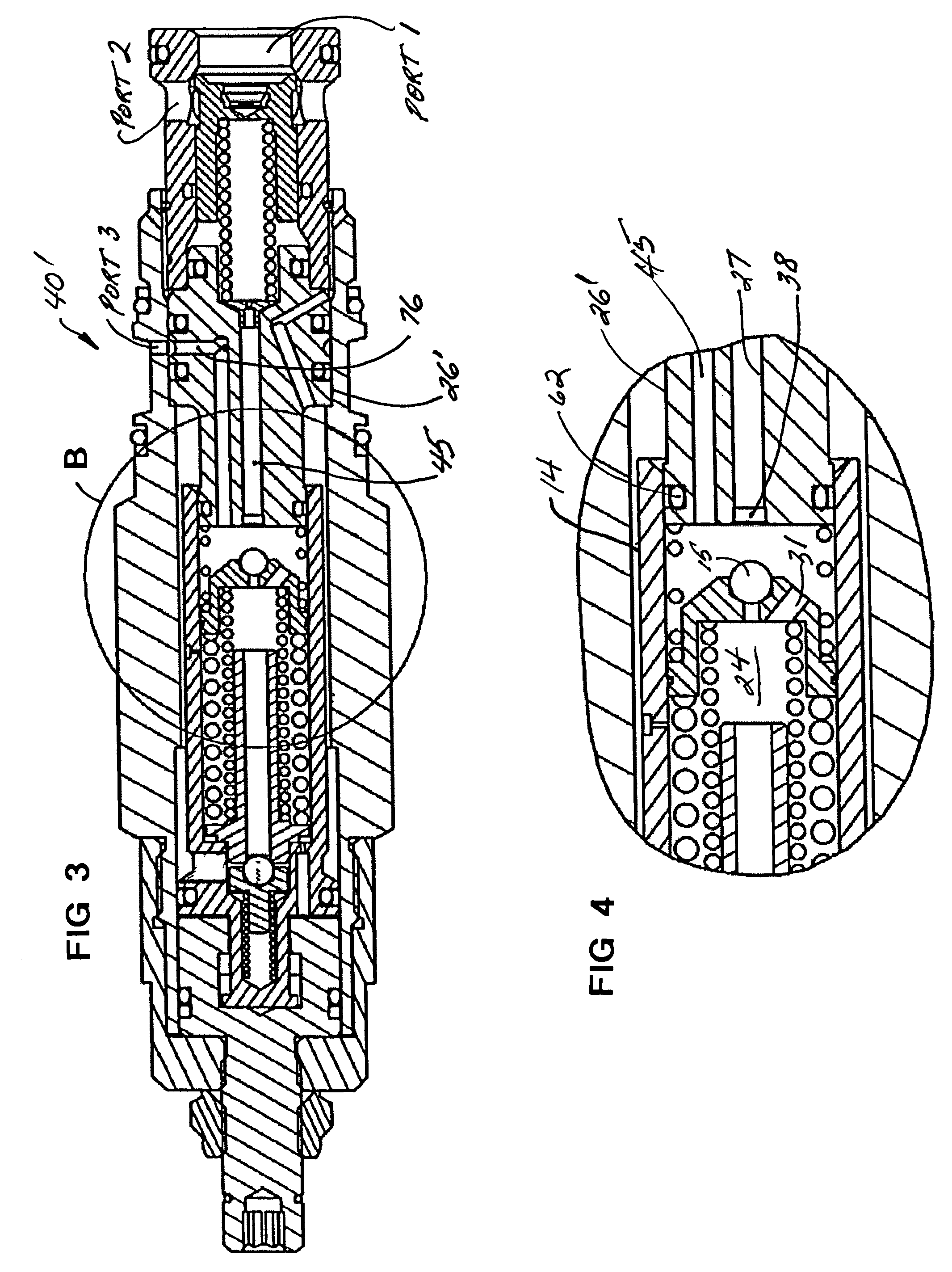
[0045]In the preferred embodiment, the effective area for the pilot pressure to act upon is with respect to the open end surface 29 of the sleeve 14 which defines a differential ring area. The outer diameter of the sleeve 14 is 0.747″; the inner diameter of the sleeve 14 and the outer diameter of the retainer 26 is 0.500″. The differential area, therefore, is about 0.242 sq. inch. That means a pilot chamber pressure of 225 p.s.i. exerts a force of about 54 lbs. against pilot piston 37 which is exerted against the pilot ball 15. The pilot ball seat diameter is 0.092″ which defines an effective area of 0.0066 sq. inch. The pilot spring force of 54 lbs. spring force sets the valve at an operating pressure of 8181 p.s.i. The pressure in the pilot chamber 24 of 225 p.s.i. is additive to this setting so that the theoretical maximum operating pressure setting of the valve is about 8400 p.s.i. The actual maximum pressure is limited by the spring load, the pilot springs 13 and 33 apply to th...


PUM


Abstract

A pilot operated pressure valve which limits the rate of pressure rise and substantially eliminates excessive system and tank pressure spikes. Because the pilot ball downstream of the damping orifice is held off the pilot seat in the normal starting condition by a pilot return spring, the main piston will open immediately when system pressure overcomes the low bias pressure of the main spring. A pilot pressure bypass port, which selectively deactivates the pilot chamber features, may also be included.

Description

CROSS-REFERENCE TO RELATED APPLICATIONS[0001]Not applicableSTATEMENT REGARDING FEDERALLY SPONSORED RESEARCH OR DEVELOPMENT[0002]Not applicableINCORPORATION-BY-REFERENCE OF MATERIAL SUBMITTED ON A COMPACT DISC[0003]Not applicableBACKGROUND OF THE INVENTION[0004]1. Field of the Invention[0005]This invention relates generally to pressure control valves in hydraulic systems, and more particularly to a soft ventable relief valve which eliminates pressure spikes and hydraulic shock in such systems.[0006]2. Description of Related Art[0007]Pressure relief valves are used to provide a quick opening for excessive hydraulic pressure in a hydraulic system into which the valve is installed. These valves are characterized by a structure by which hydraulic pressure in the system is regulated by relieving and venting some of the pressurized fluid back to a supply tank or reservoir.[0008]All conventional relief valves such as a differential piston relief valve or a pilot operated relief valve have a...

Claims


Application Information

Patent Timeline
Patent Type & Authority Patents(United States)
IPC IPC(8): F16K17/10
CPCF16K17/0433Y10T137/777Y10T137/7766
Inventor PRINSEN, TODDZAHE, BERND
Owner SUN HYDRAULICS LLC
Learn More