Device for handling a workpiece during a shaping process

a technology for shaping and workpieces, applied in the direction of positioning devices, metal-working feeding devices, gripping heads, etc., can solve the problem of reducing the load on the drives

Active Publication Date: 2008-12-30
LANGENSTEIN & SCHEMANN
View PDF10 Cites 6 Cited by
  • Summary
  • Abstract
  • Description
  • Claims
  • Application Information

AI Technical Summary

Benefits of technology

[0011]The object of the present invention is to enable more complex motions of the workpiece during the shaping process, in particular before a shaping step or between two shaping steps, in particular, to enable rotation of the workpiece. In addition, preferably the handling device known from DE 100 60 709 A1 is to be correspondingly refined.

Problems solved by technology

If the gripper now places a forged workpiece on a forging die of a forging hammer, and the striking tool strikes the workpiece, vibrations or impacts thus produced which are transmitted to the vise-grip pincers and gripper may become damped and absorbed in the elastic block piece, thereby relieving the load on the drives.

Method used


Image

  • Device for handling a workpiece during a shaping process
  • Device for handling a workpiece during a shaping process
  • Device for handling a workpiece during a shaping process

Examples


Embodiment Construction

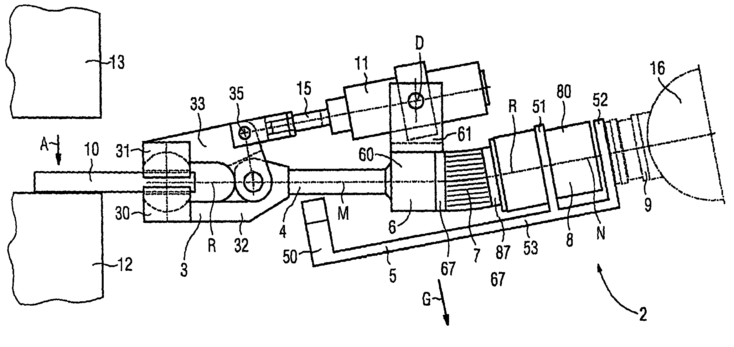
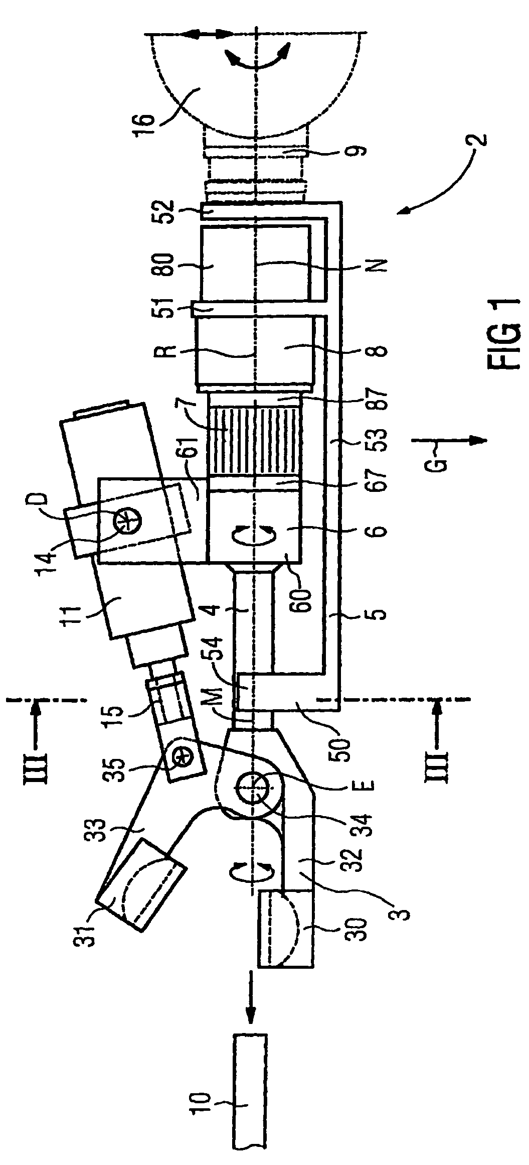
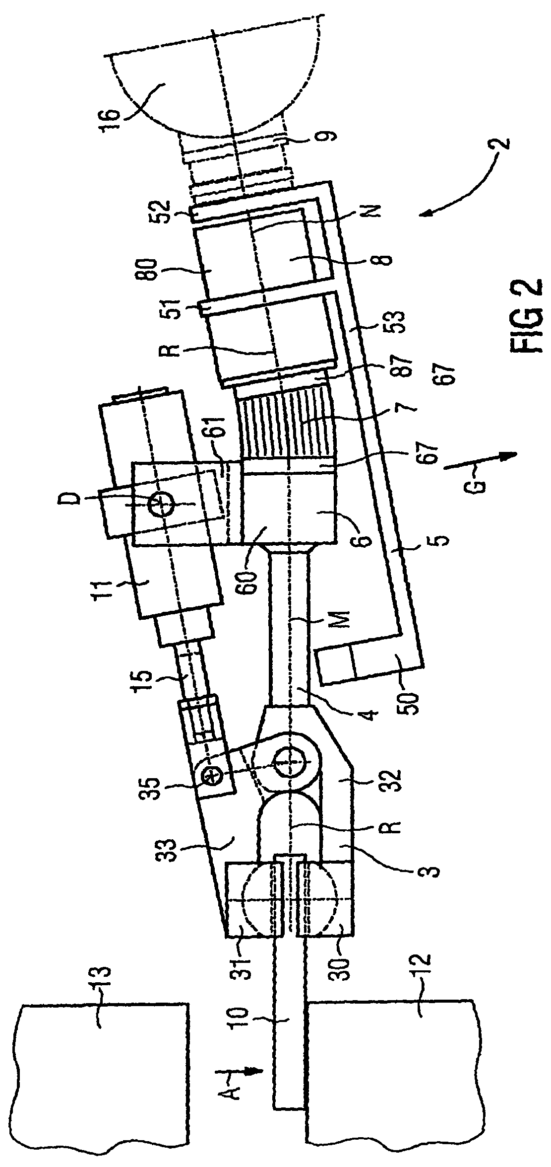
[0050]each in schematic representation. Corresponding variables and parts are provided with identical reference numbers in FIGS. 1 through 4. A handling device (or manipulator, robot) is designated by reference number 2, a gripping mechanism (or gripping pincers) by 3, a support shaft (or transmission shaft) by 4, a support device (or rigid control device) by 5, a carrier part by 6, a flexible element by 7, a rotary drive by 8, an articulated joint by 9, a workpiece by 10, an actuating device for opening and closing the gripping mechanism 3, by 11, a lower tool (or forging die) of a forging hammer by 12, an upper tool of the forging hammer by 13, and a conveying device by 16.

[0051]The gripping mechanism 3 comprises two gripping levers (or pincer levers) 32 and 33 which are able to swivel with respect to one another about a swivel axis E in a swivel bearing 34 for opening and closing the gripping mechanism 3. A gripping jaw (or gripping element, pincer jaw) 30 or 31 is provided on ea...


PUM

PropertyMeasurementUnit
rotationaaaaaaaaaa
swivel angleaaaaaaaaaa

Abstract

A device for handling a workpiece during a shaping process includes at least one gripping mechanism having at least two gripping elements that can move relative to one another for grasping the workpiece; at least one conveying device for conveying the gripping mechanism or at least one support apparatus to which the gripping mechanism is or may be attached; and at least one rotary drive for rotating the gripping mechanism about a rotational axis that extends through the gripping mechanism, and/or for rotating at least one of the gripping elements about a rotational axis that extends through the gripping element. The conveying device and the gripping mechanism can be connected to one another in a flexible manner in a flexible state while being positioned relative to one another in a rigid manner at least in one three-dimensional direction.

Description

[0001]This application is a 35 USC 371 of PCT / EP04 / 05780 filed May 8, 2004.BACKGROUND OF THE INVENTION[0002]1. Field of the Invention[0003]The invention relates to a device for handling a workpiece during a shaping process.[0004]2. Background and Related Art[0005]DE 42 20 796 A1 discloses a handling device for holding a forged piece during a forging process, in which a traveling mechanism carries a gripping mechanism via a sleeve, the gripping mechanism having vise-grip pincers that grasp the forged piece during the forging process. The sleeve has a hydraulic chamber, and optionally may be brought into a flexible state and a rigid state by changing the internal pressure in the hydraulic chamber via a control valve.[0006]A further device for handling a forged piece during a forging process is known from DE 100 60 709 A1, in which an oblong gripper on its one end is mounted on a support apparatus, and on its other end has a gripping mechanism with vise-grip pincers, between whose two ...

Claims


Application Information

Patent Timeline
Patent Type & Authority Patents(United States)
IPC IPC(8): B21D43/10B21J13/10B25J15/00B25J19/00
CPCB21J13/10B25J15/00B25J19/0091
Inventor REISSENWEBER, FRANK
Owner LANGENSTEIN & SCHEMANN
Why Eureka
Try Eureka