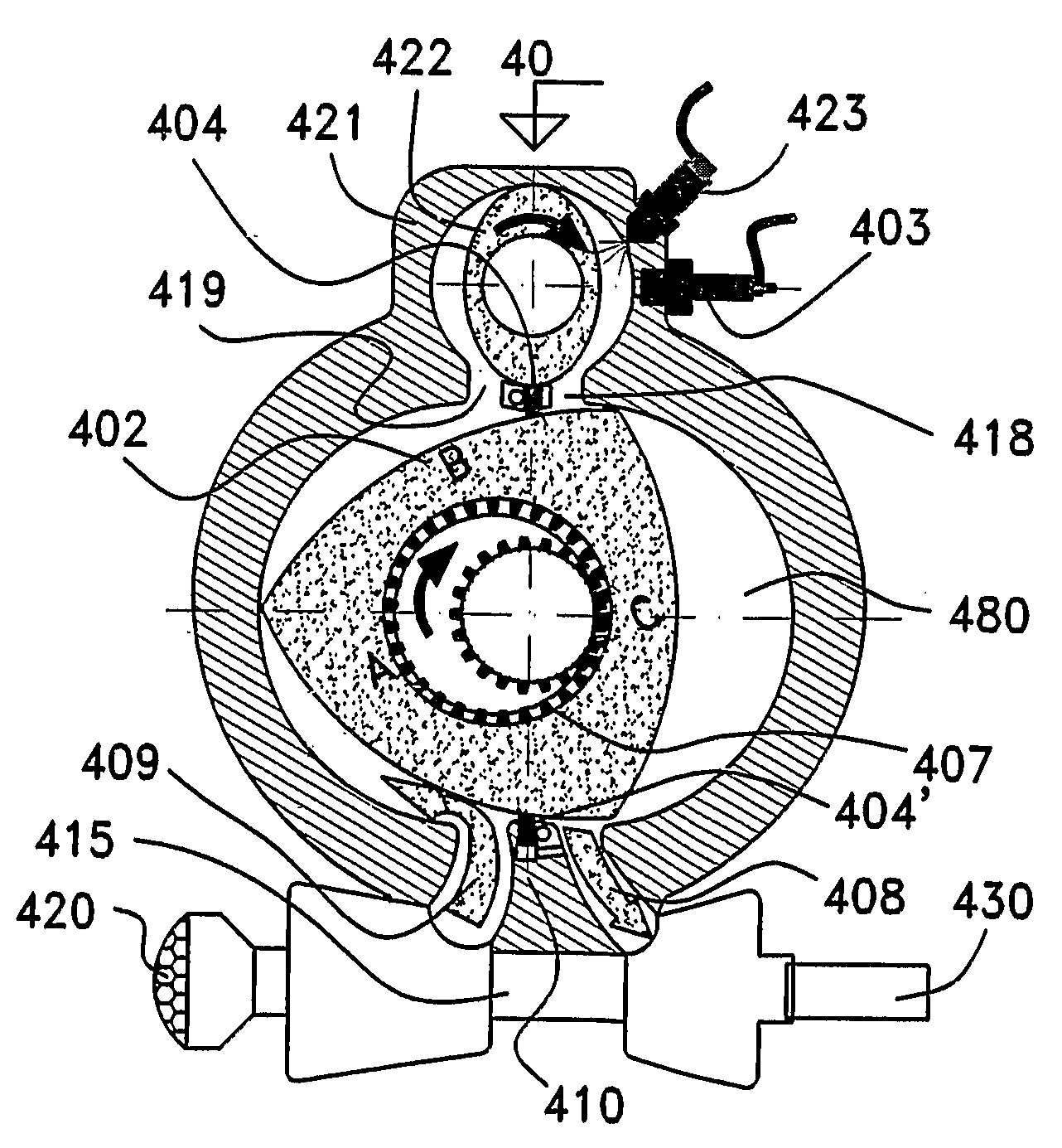
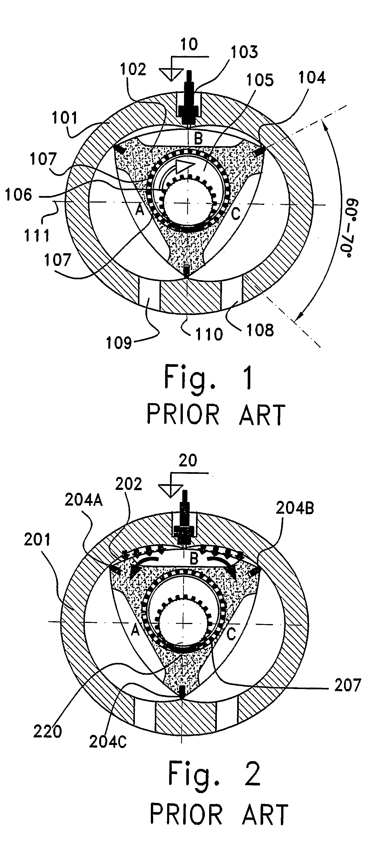
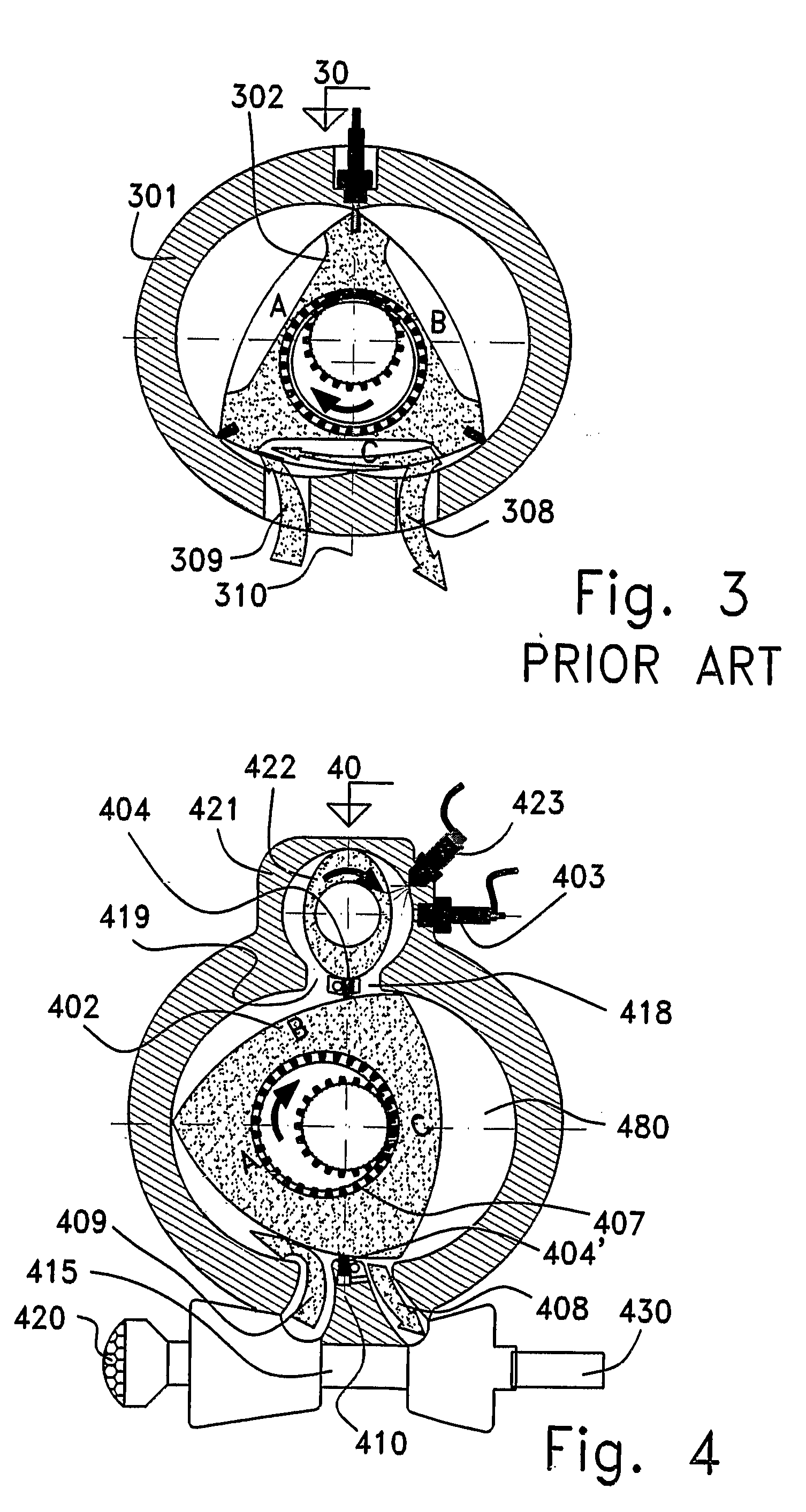
After many years of Wankel engine development, there are some practical limitations that prevent its widespread acceptance, despite its theoretical advantages with respect to a reciprocating piston engine.
Consequently, only a limited number of manufacturers are involved with Wankel engine production.
Some of the Wankel
rotary engine limitations relate to its rotor apex seals, as expressed by the following characteristics:Tendency to bounce over housing internal contour;Incompatibility of a suitable material for the apex seal with that of the rotor housing;Damage to the internal contour of the rotor housing and to the seals;Speed limitations due to high centrifugal forces;Poor sealing at a low rotational speed and under sudden changes of operational conditions such as acceleration and deceleration and of engine load; andSealing limitations of the apex seal when the engine is exposed to a relatively
high pressure, which is characteristic of Diesel engines.
All of the above-mentioned limitations result in inadequate sealing that leads to low reliability and
short duration of operation, defined also as a short time between overhauls (TBO).
Other known drawbacks of prior art Wankel rotary engines are:The
combustion chamber is not optimally configured for its function, and is therefore one of the main reasons for its inability in achieving efficient combustion and for its relatively low
thermal efficiency.A tendency to mix intake charge with burnt exhaust gases during exhaust-intake overlap, which reduces
engine efficiency and output.
The utility of a
turbocharger, which further mixes the intake charge with the exhaust gases, is reduced since a greater percentage of the burnt gas is forced thereby to remain in the engine, to drift by the motor rotor to the intake section thereof, and to mix with the intake charge.A
high surface to volume ratio, resulting in fuel condensation on the inner walls of the working volumes, which is particular noticeable in water-cooled engines and negatively influences efficiency and wear.At the beginning of each
work cycle, a noticeable conflict is characteristic of prior art Wankel engines resulting in inefficient utilization of
combustion products, between the geometrical position of the rotor during ignition to the direction of the driving forces generated by the
combustion products.
When the leaning angle is approximately 60 degrees, substantially all of the combustion forces support the rotation of the rotor; however, the remaining pressure of the
combustion products is very low at such a leaning angle indicating that the
work cycle is about to end.In addition to the previously mentioned conflict, substantially all of the combustion pressure is generated, immediately after ignition, over the rotor and perpendicularly to the main shaft, imposing a very
high load and stress to the engine
system which must be taken into consideration during the engine
system design.The effective
work cycle sector of prior art Wankel engine is considerably narrow, beginning after an apex of the rotor has passed the
minor axis by about 60 degrees and ending after about 60 degree of rotation, where the same apex reaches the point which start to
expose the exhaust port.The
compression ratio of prior art Wankel
rotary engine depends on the K factor (defined as ratio of the rotor
radius to eccentricity).
In order to achieve reasonably good results with a prior art Wankel engine, limiting compromises must be made.The eccentric motion of the rotor drive system
assembly of the Wankel engine results in restrictions to engine speed, and poses dynamic balancing problems.
The complex motion of the rotor and the eccentric shaft
assembly results in a shaft speed three times higher than that of the rotor, thereby resulting in a low torque-high speed engine shaft
power take off (P.T.O.)

