Electrically conductive gasket

a technology of electrical conductivity and gaskets, applied in the field of gaskets, can solve the problems of electromagnetic interference (emi), the list of electrical components seems endless and continues to grow, and the need to solve additional problems

Active Publication Date: 2008-12-30
JEMIC SHIELDING TECH
View PDF25 Cites 62 Cited by
  • Summary
  • Abstract
  • Description
  • Claims
  • Application Information

AI Technical Summary

Benefits of technology

[0015]Yet another embodiment of the present invention comprises a gasket for attachment to an electrically conductive object. The gasket includes a core that has a perimeter and an attachment portion. An electrically conductive cover is wrapped around the perimeter of the core. The electrically conductive cover has a first end flap and a second end flap wherein the second end flap covers at least a portion of the attachment portion of the core. A first adhesive is applied on the portion of the second end flap covering the attachment portion for attaching a portion of the first end flap thereto to retain the electrically conductive cover on the core. A portion of the first adhesive is exposed for affixing the gasket to the electrically conductive object and retains at least one of the first and second end flaps in contact with the electrically conductive object.

Problems solved by technology

Indeed, the list of electrical components seems endless and continues to grow.
With the development and use of such a myriad of electronic components came additional problems that had to be solved to effectively use such components to achieve desired results.
An example of one problem is the occurrence of electromagnetic interference (EMI) which is an undesirable electric disturbance that is induced or radiated from electric or electronic devices.
Such EMI problems commonly manifest themselves when several electrical components are located in close proximity to one another wherein the EMI radiating from one component hampers or debilitates the effective operation of another component mounted nearby.
Such attachment approaches, however, can undesirably form a barrier between the electrically conductive cover material 3 and the electrically conductive surface 10.
If a conductive path is not established between the cover material 3 and the conductive surface 10 to which the gasket 1 is attached, the gasket's effectiveness is compromised and, in extreme cases, may be destroyed.
Furthermore, if an electrically conductive adhesive is employed to affix the gasket 1 to the electrically conductive surface 10 and to establish an electrically conductive path therebetween, migration of the electrically conductive particles in the adhesive material can occur and compromise the integrity of the electrically conductive path.
However, this approach may also have undesirable limitations.
Moreover, the tolerances that are commonly attainable utilizing known gasket manufacturing processes, make this gasket difficult to manufacture in relatively small sizes.
In addition, if the compression forces applied to the gasket when in use are not uniformly applied across the gasket, “rocking” may occur which results in one or more portions of the gasket being moved out of contact with the surface to which it is to be attached.
In addition, the shape of the gasket limits the types and shapes of mechanical fasteners that may be employed to attach the gasket to an object.

Method used


Image

  • Electrically conductive gasket
  • Electrically conductive gasket
  • Electrically conductive gasket

Examples


Embodiment Construction

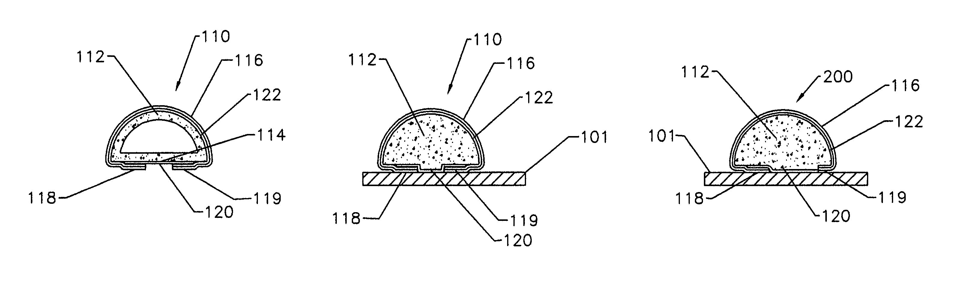
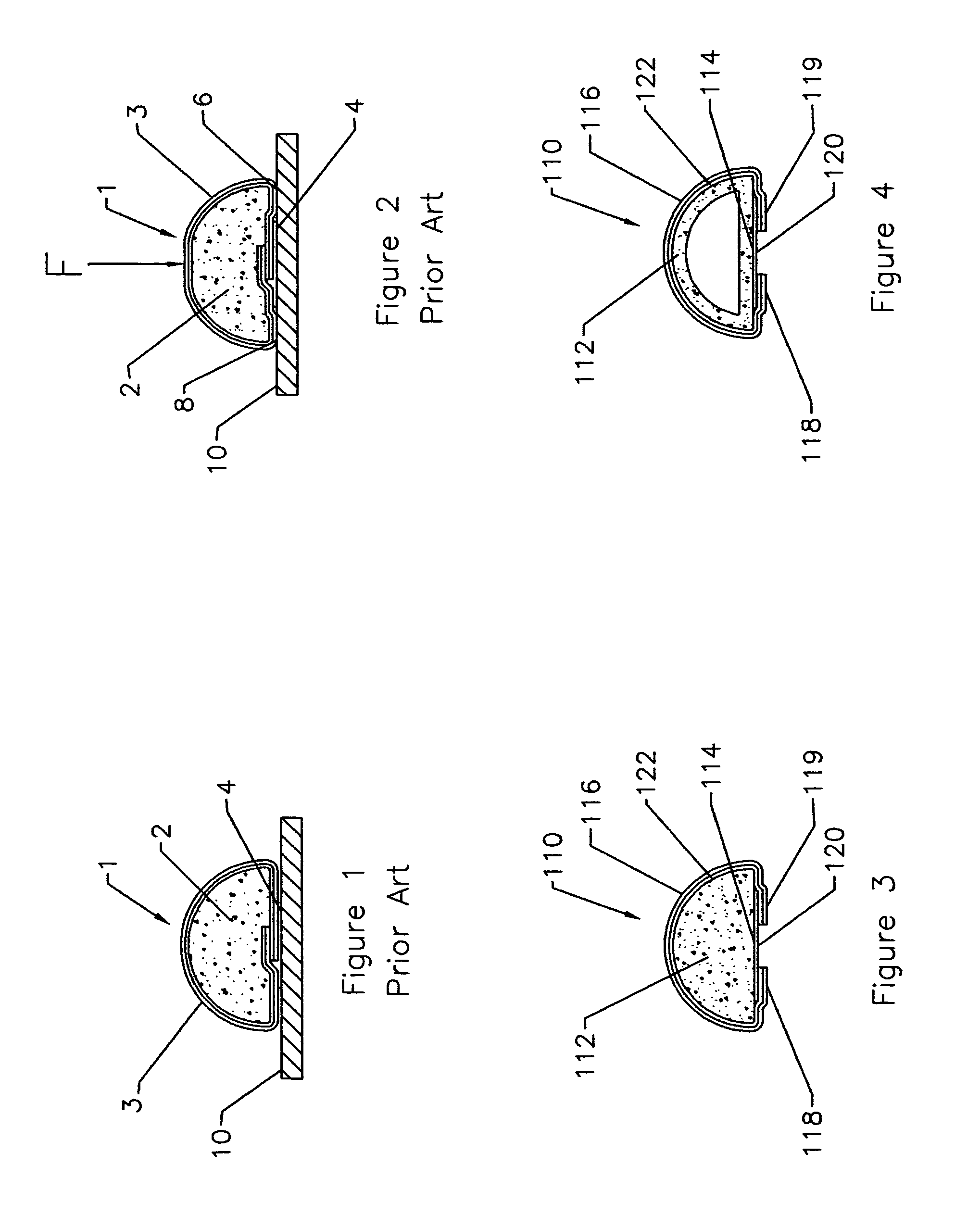
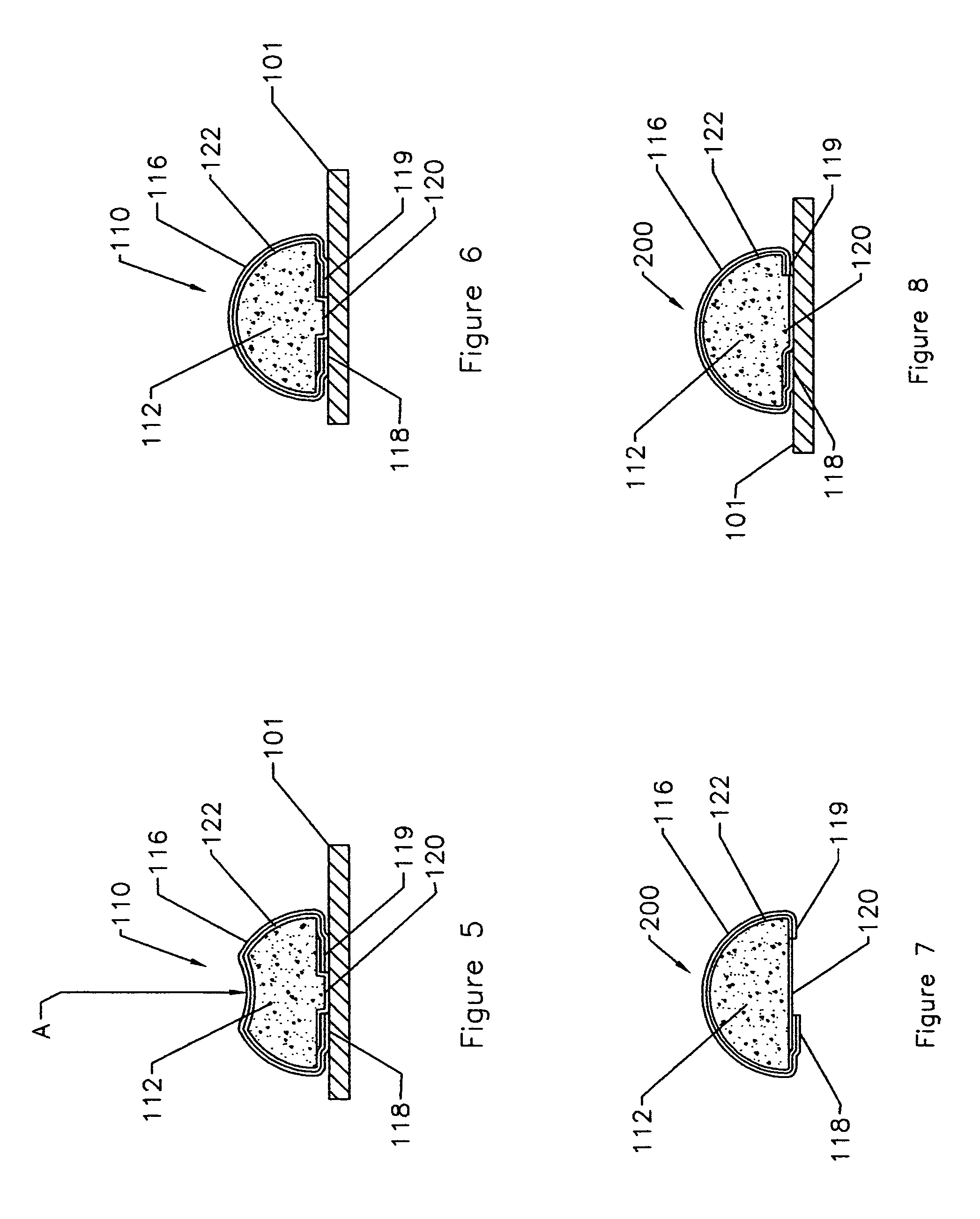
[0054]Referring now to the drawings for the purposes of illustrating embodiments of the invention only and not for the purposes of limiting the same, FIGS. 3-6 illustrate a gasket assembly 110 comprising one embodiment of the present invention which may be attached to an electrically conductive object 101 such as a portion of a housing used to house electrical components. As the present Detailed Description proceeds, the reader will appreciate that the various embodiments of the present invention may be effectively employed for example, to seal the interface between an enclosure and a door or panel, but various embodiments may also find use in other applications such as providing electrical continuity between two adjoining panels, such as walls in a shielded room, or providing a conductive environmental seal between two adjoining equipment sections. Thus, as used herein, the term “electrically conductive object” can refer to any object that may conduct electricity.

[0055]In this embo...


PUM


Abstract

An electrically conductive gasket and methods of manufacturing electrically conductive gaskets. In one embodiment, the gasket includes a core that supports an electrically conductive cover thereon. The electrically conductive cover may be attached to the core or portions of the core by one or more adhesives used to also affix the gasket to an electrically conductive object. In other embodiments, a mechanical fastener may be affixed to the core by the one or more adhesives employed to affix the electrically conductive cover to the core.

Description

BACKGROUND[0001]1. Field of the Invention[0002]Various embodiments of the subject invention relate to gaskets and, more particularly, to gaskets for inhibiting and preventing leakage of Electromagnetic Interference (EMI) and radio frequency radiation (RFI) between two surfaces or components.[0003]2. Description of the Invention Background[0004]Ever since Benjamin Franklin flew his famous kite in a lightening storm and discovered electricity, countless numbers of electrically powered devices and components have been developed to make man's life easier. Such components range from, for example, motors, switches, relays, timers, computers, etc. Indeed, the list of electrical components seems endless and continues to grow.[0005]With the development and use of such a myriad of electronic components came additional problems that had to be solved to effectively use such components to achieve desired results. An example of one problem is the occurrence of electromagnetic interference (EMI) w...

Claims


Application Information

Patent Timeline
Patent Type & Authority Patents(United States)
IPC IPC(8): H05K9/00
CPCH05K9/0015Y10S277/92
Inventor DIETRICH, JOHN F.HAMMAKER, CLARK S.
Owner JEMIC SHIELDING TECH
Why Eureka
Try Eureka