Distance measuring device

a technology of distance measurement and measuring device, which is applied in the direction of distance measurement, instruments, surveying and navigation, etc., can solve the problems of measurement error, difficult to perform high speed distance measurement, and difficulty in high speed distance measuremen

Active Publication Date: 2009-01-06
KK TOPCON
View PDF17 Cites 84 Cited by
  • Summary
  • Abstract
  • Description
  • Claims
  • Application Information

AI Technical Summary

Benefits of technology

[0085]The present invention provides the distance measuring device as described above, wherein there is provided a light amount adjusting means for changing a light amount of the internal reference light on an optical path where the reference reflection unit is provided. As a result, it is possible to obtain the internal reference light to match the light amount of the reflected distance measuring light, and this contributes to the improvement of reliability of measurement.

Problems solved by technology

Also, in the distance measurement, drift of detection circuit or the like within the distance measuring device exerts influence and causes measurement error.
Because optical path switching and light amount adjustment are both performed mechanically, it is difficult to carry out optical path switching and light amount adjustment at high speed, therefore it is difficult to perform distance measurement at high speed.
For this reason, although there is no problem when distance is measured on an object to be measured such as a building, the measurement may be difficult to perform when high speed distance measurement is required, e.g. in case distance should be measured continuously on a plurality of moving objects, such as bulldozers, by using a single measuring device.
In case that surveying is carried out on a moving object etc., optical path switching speed and light amount adjusting speed cannot follow the moving speed of the moving object, and there are problems that distance cannot be measured in such cases.

Method used


Image

  • Distance measuring device
  • Distance measuring device
  • Distance measuring device

Examples


Embodiment Construction

[0027]Description will be given below on the best mode for carrying out the present invention referring to the drawings.

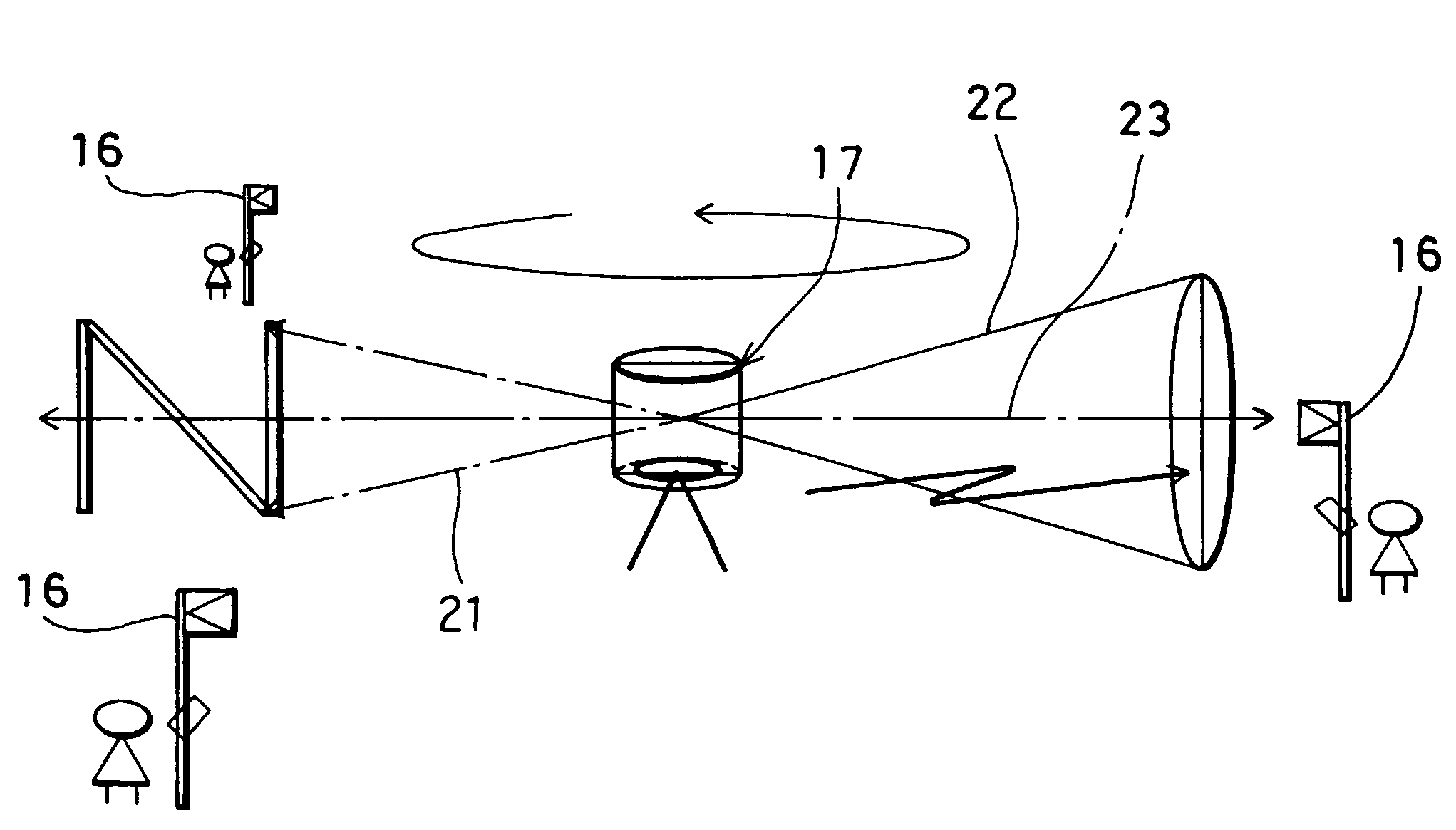
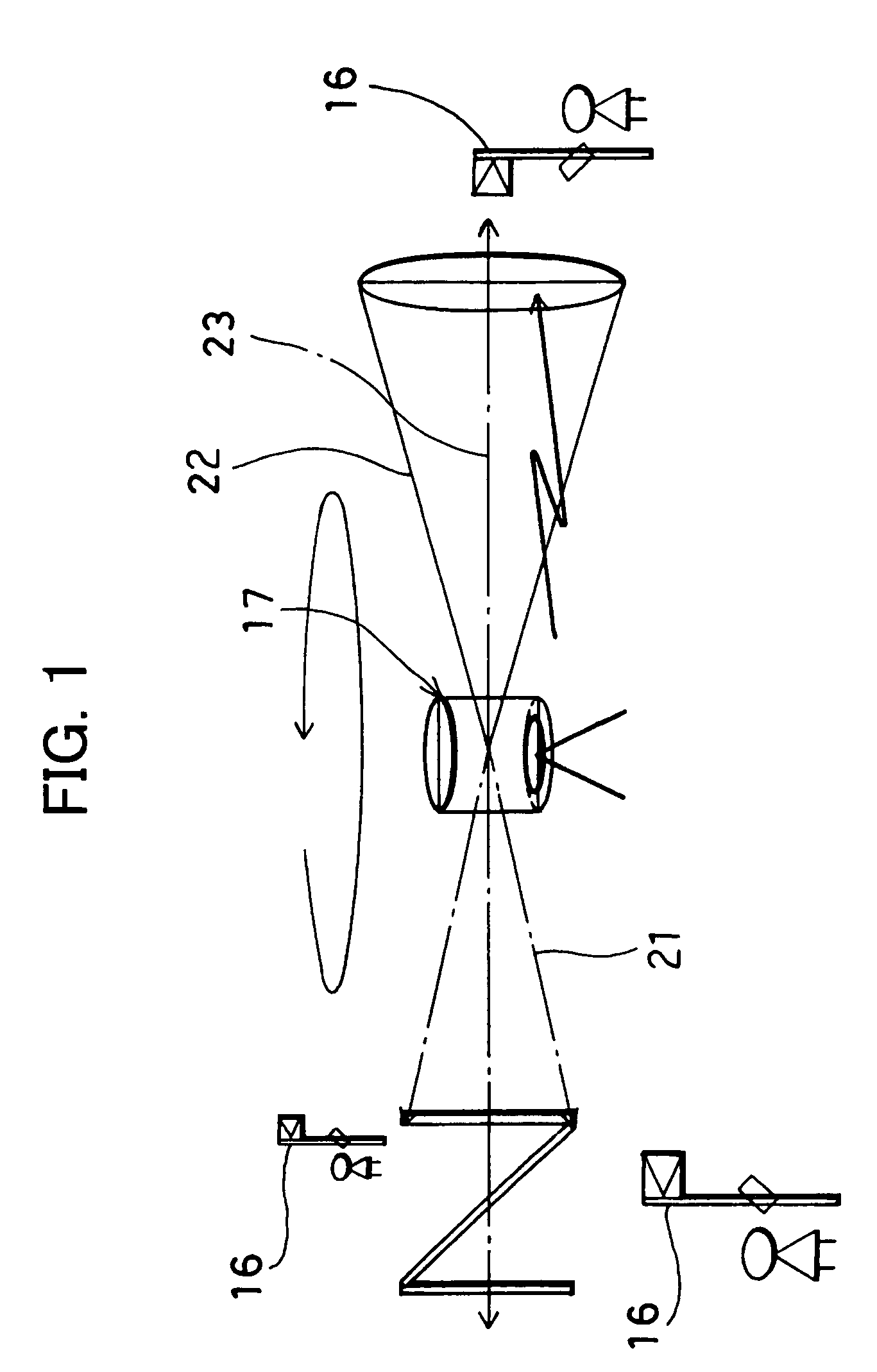
[0028]First, description will be given on general outline of measurement in the embodiment of the present invention referring to FIG. 1.

[0029]In a distance measuring device 17 shown in FIG. 1, a horizontal reference plane is formed, and a distance to an object 16 to be measured can be measured.

[0030]The distance measuring device 17 comprises a reference plane forming unit (not shown) and a distance measuring unit 19 (to be described later). The distance measuring device 17 projects a laser beam 21 for forming a reference plane by rotary irradiation, and a distance measuring light 22 can be projected by rotary irradiation. By the distance measuring light, distances to the objects 16 to be measured at a plurality of points can be measured.

[0031]The reference plane forming unit projects the laser beam 21 for forming reference plane by rotary irradiation and forms a ho...


PUM


Abstract

The present invention provides a distance measuring device, which comprises a light projecting unit for projecting a distance measuring light (22) to an object to be measured, a reference reflection unit (55) provided relatively movable and arranged at a known position so as to traverse the projected distance measuring light, a photodetection unit (7) for receiving a reflection light from the object to be measured as a reflected distance measuring light (22′) and a reflection light from said reference reflection unit as an internal reference light (22″), and a control arithmetic unit (15) for calculating a distance to the object to be measured based on a photodetection signal relating to the reflected distance measuring light and based on a photodetection signal relating to the internal reference light.

Description

FIELD OF THE INVENTION[0001]The present invention relates to a distance measuring device for measuring a distance by projecting a laser beam to an object to be measured and by receiving a reflection light from the object to be measured.BACKGROUND ART[0002]As a distance measuring device, a light wave distance measuring device is known. In the light wave distance measuring device, a laser beam is projected to an object to be measured and a distance to the object to be measured is determined by using a reflection light from the object to be measured.[0003]In the light wave distance measuring device known in the past, intensity of the laser beam is modulated at a fixed frequency, and the laser beam is projected as a distance measuring light. A reflected distance measuring light reflected by the object to be measured is received. A phase of intensity modulation of the reflected distance measuring light thus received is compared with a phase of intensity modulation of an internal referenc...

Claims


Application Information

Patent Timeline
Patent Type & Authority Patents(United States)
IPC IPC(8): G01C3/08
CPCG01C3/08G01S7/497G01S17/36G01S17/42G01C15/002
Inventor OHTOMO, FUMIOMIKI, NAOTO
Owner KK TOPCON
Why Eureka
Try Eureka