Electro-Optical Distance Meter

Active Publication Date: 2016-09-08
KK TOPCON
View PDF0 Cites 27 Cited by
  • Summary
  • Abstract
  • Description
  • Claims
  • Application Information

AI Technical Summary

Benefits of technology

[0015]Further, according to the present invention, in the electro-optical distance meter, the arithmetic control unit performs distance measurement at a delay time of a photodetection pulse of the intermittent modulated distance measuring light. As a result, a long distance measurement is possible, and a modulated frequency required for long distance measurement can be omitted.
[0016]Further, according to the present invention, in the electro-optical distance meter, the arithmetic control unit produces an abnormal signal in a case where the difference between the precise measurement distance value and the coarse measurement dist

Problems solved by technology

In a conventional electro-optical distance meter, since a plurality of frequencies are prepared, distance measuring light is projected per each plurality of fre

Method used


Image

  • Electro-Optical Distance Meter
  • Electro-Optical Distance Meter
  • Electro-Optical Distance Meter

Examples


Embodiment Construction

[0023]A description will be given below on an embodiment of the present invention by referring to the attached drawings.

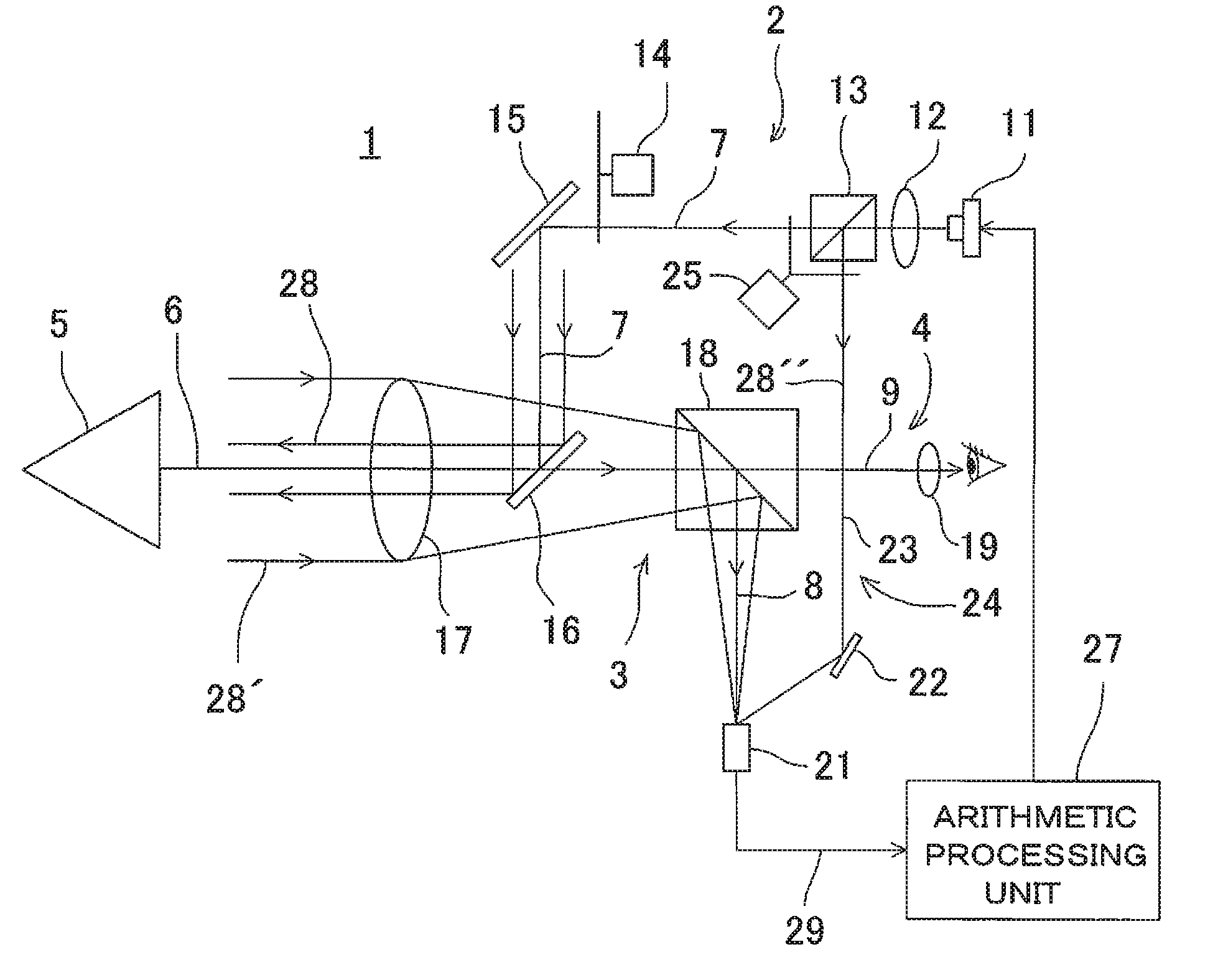
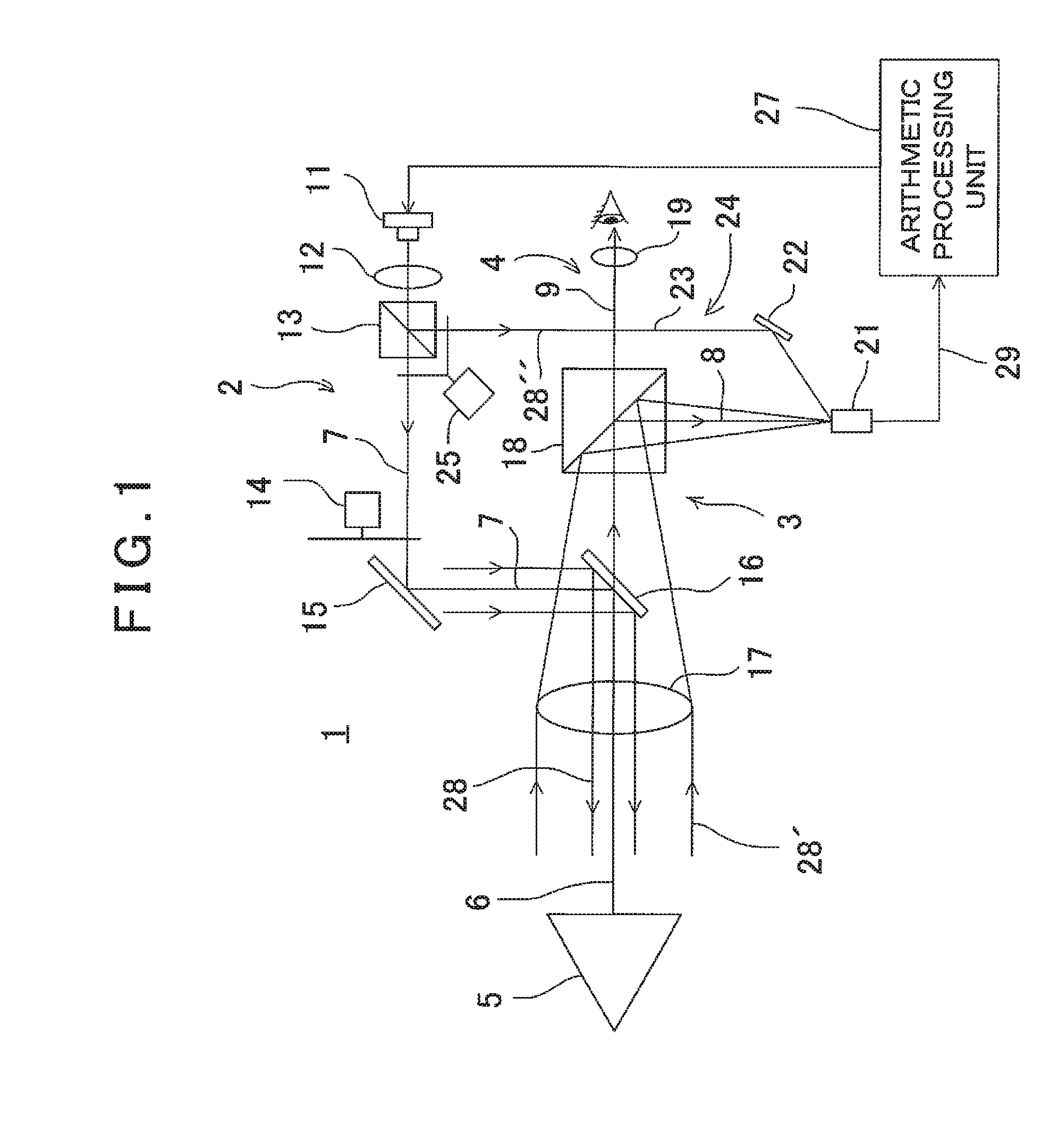
[0024]First, referring to FIG. 1, a description will be given on a distance measuring optical system 1 of an electro-optical distance meter according to an embodiment of the present invention.

[0025]In FIG. 1, the distance measuring optical system 1 comprises a projecting optical system 2, a photodetecting optical system 3 and a sighting optical system 4. Further, FIG. 1 shows that an object to be measured 5 is a prism as a retro-reflector.

[0026]The distance measuring optical system 1 has a distance measuring optical axis 6 directed to the object to be measured 5 and the projecting optical system 2 has a projecting optical axis 7, the photodetecting optical system 3 has a photodetection optical axis 8, and the sighting optical system 4 has a sighting optical axis 9.

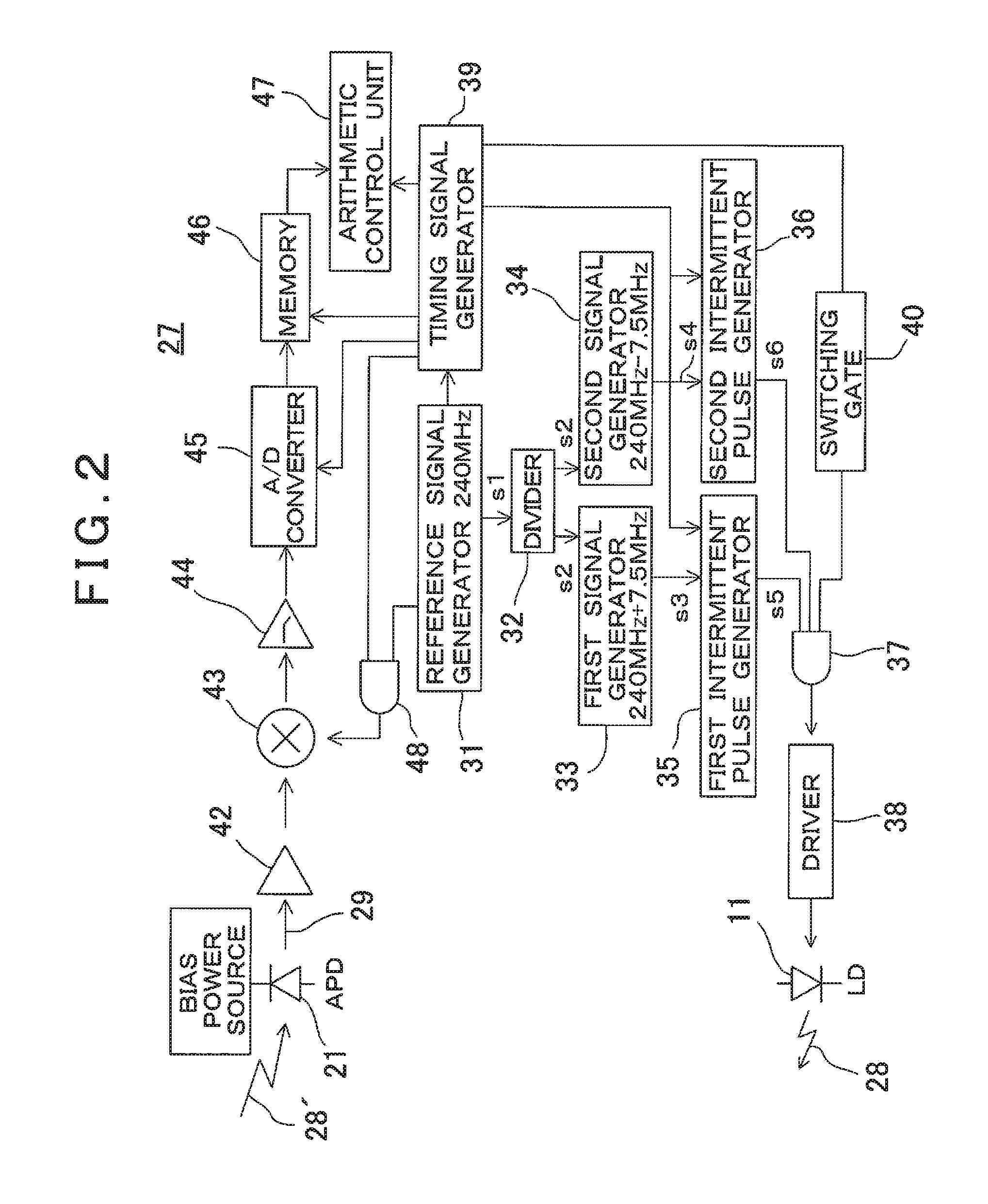
[0027]Along the projecting optical axis 7, a light emitting element 11, a condenser lens 12, a half mi...


PUM


Abstract

The invention provides an electro-optical distance meter comprising a light emitting element for emitting a distance measuring light, signal generators for generating two or more proximity frequencies, a modulation signal in which the two or more proximity frequencies are intermitted respectively and converted to pulses with a predetermined width, a projecting optical system for sequentially switching over and projecting intermittent modulated distance measuring light as converted to pulses with predetermined width by the modulation signal, a photodetection unit for receiving a reflected distance measuring light from an object to be measured and producing an intermittent photodetection signal with a predetermined pulse width, a reference signal generator for issuing reference frequency signals having a difference of a predetermined frequency respectively, a frequency converting unit for performing frequency conversion by mixing the intermittent photodetection signals from the photodetection unit and the reference frequency signals, corresponding to each intermittent frequency signals respectively and obtaining intermittent conversion signals with a pulse width, and an arithmetic control unit, wherein the pulse width of the intermittent photodetection signal is set up so as to be longer in a time duration than a period of the intermittent conversion signal, and in a case where the object to be measured is a moving object, the period of the intermittent photodetection signal is set to such speed that a phase change of the intermittent conversion signal due to moving of the moving object can be negligible, wherein the arithmetic control unit is configured so as to calculate a precise measurement distance value by obtaining the phase of the intermittent photodetection signal with respect to the two or more proximity frequencies, to calculate a coarse measurement distance value by obtaining a phase difference between the intermittent conversion signals, and to determine a distance by combining the coarse measurement distance value and the precise measurement distance value.

Description

BACKGROUND OF THE INVENTION[0001]The present invention relates to an electro-optical distance meter, which projects a modulated measuring light to an object to be measured, receives a reflected measuring light from the object to be measured and measures a distance to the object to be measured by a phase difference between the measuring light and the reflected measuring light.[0002]In the electro-optical distance meter which perform a distance measurement by detecting the phase difference between the measuring light and the reflected measuring light, a distance as measurable and a measurement accuracy are determined by a modulated frequency. For this reason, in order to make measuring from a near distance to a long distance possible, it is necessary to project a distance measuring light with a plurality of modulated frequencies.[0003]For instance, in a case where a modulated frequency of 30 MHz and a modulated frequency of 300 KHz are used, a distance up to 5 m and a distance up to 5...

Claims


Application Information

Patent Timeline
IPC IPC(8): G01S7/486G01S17/36G01S7/4865G01S7/4915G01S17/26
CPCG01S17/36G01S7/4865G01S17/10G01S7/4915G01S7/497G01S17/26
Inventor OHTOMO, FUMIOKUMAGAI, KAORU
Owner KK TOPCON
Why Eureka
Try Eureka