Arrangement for measuring the level of contents in a container

a technology for arranging and measuring the level of contents in containers, applied in the direction of engine lubrication, liquid/fluent solid measurement, reradiation, etc., can solve the problems of unfavorable use of echo, inability to achieve, and prove to be difficult or impossible in large containers, etc., to achieve the effect of eliminating the measurement error

Inactive Publication Date: 2005-02-17
EHNDRESS KHAUZER GMBKH KO KG
View PDF1 Cites 27 Cited by
  • Summary
  • Abstract
  • Description
  • Claims
  • Application Information

AI Technical Summary

Benefits of technology

It is an object of the invention to permit automatic checking of the measured result and, if necessary, the elimination of a measuring error in an arrangement suitable for continuous measurement of the contents level in a container in accordance with the transit time principle, irrespective of the size of the container and the type and properties of the material in, the container.
With the arrangement according to the invention, a continuous plausibility check of the measuring result of the continuous contents level measurement can be carried out on the basis of the contents level displays of one or of several limit sensors, and this check is the more accurate the greater the number of limit sensors used is. Furthermore, each time the contents level in the container changes, each limit sensor gives an exact contents level measured value when the contents level is identical with the level to be monitored by the limit sensor. A comparison of this measured value with the measured value supplied simultaneously by the level measuring device can show whether there has been a measuring error, and when a predefined error limit is exceeded, measures can be initiated to eliminate the measuring error, or a warning or error message can be displayed. This allows the field of application of continuously measuring level measuring devices to be extended and the measuring reliability to be increased under difficult application conditions.

Problems solved by technology

A precondition for this prior art technique is that a tube is fixed in the container extending more or less over the whole height of the container.
This represents no problem in small containers, such as fuel tanks in vehicles or airplanes, but often proves to be difficult or impossible in large containers.
Another precondition for this prior art technique is that the transceiver units for the waves used for the transit time measurement are located at the lower end of the tube and are thus exposed to the liquid in the container, which is not possible with aggressive or very hot materials.
A final precondition for this prior art technique is that the waves are transmitted through the liquid, which in many cases is only possible with the use of ultrasonic waves, but not with the use of very short electromagnetic waves (microwaves), such as are increasingly used for level measurement according to the transit time principle.
With this method, a precondition for correct contents level measuring is that the useful echo is unequivocally identified from the total of the echo waves received.
In practice, however, interference occurs, and this makes the evaluation of the echo function difficult or even impossible.
In particular it is not possible to assume that the useful echo is identical with the absolute maximum of the echo function.

Method used


Image

  • Arrangement for measuring the level of contents in a container
  • Arrangement for measuring the level of contents in a container
  • Arrangement for measuring the level of contents in a container

Examples


Embodiment Construction

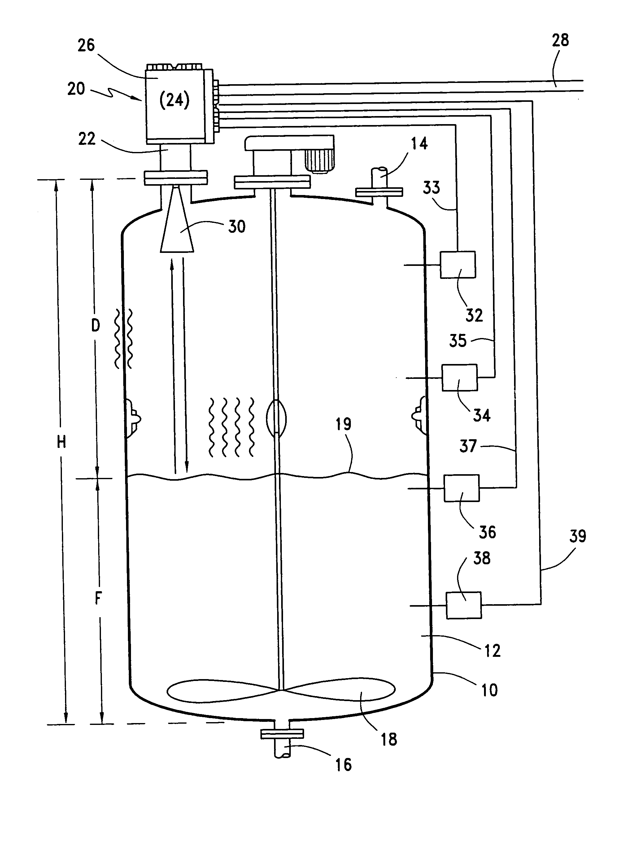
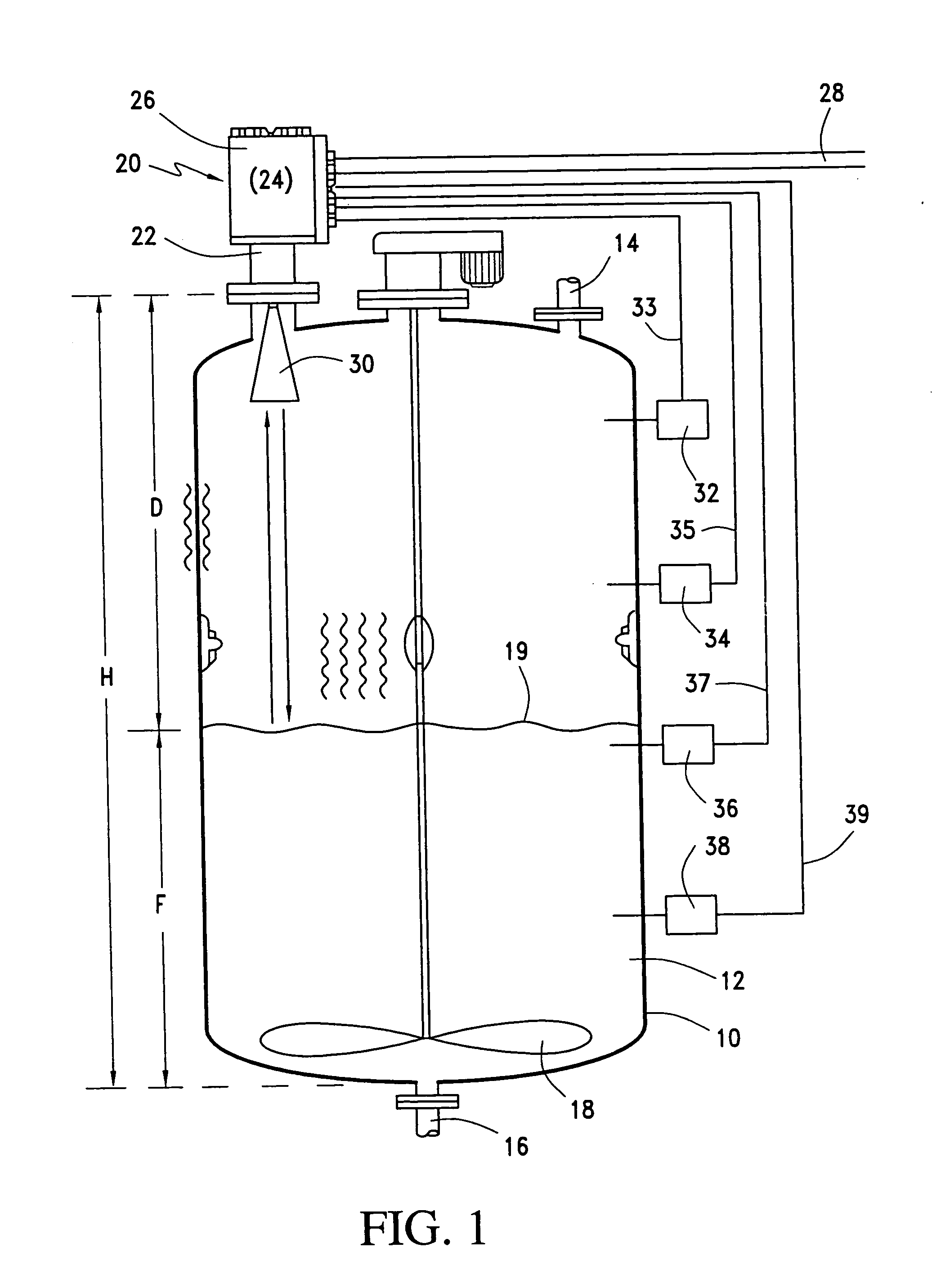
FIG. 1 of the drawing shows a container 10 which is partly filled with a material 12. The container is equipped with an inlet 14 for feeding material into the container and an outlet 16 for removing material from the container. The container may be fitted with other devices familiar to the man skilled in the art, depending on the type of material, for example with motor-driven stirring tools 18. The level F is the height of the surface of the material in the container 19 above the lowest point of the container. This level changes as material is added to the container and as material is removed from the container.

For the continuous measurement of the contents level in the container 10, a level measuring device 20 operating according to the transit time principle is located at the container above the highest possible contents level. The level measuring device 20 comprises a contents level sensor 22 which transmits waves to the material surface 19 and receives the echo waves reflected...


PUM


Abstract

A continuous measurement of the level of contents in a container is effected by a level measuring device functioning in accordance with the transit time principle by means of waves transmitted from a position located above the highest possible contents level onto the surface of the material in the container. A measuring circuit determines the contents level from the transit time of the useful echo reflected from the material surface. In addition, one or more limit sensors are located at the container, each of which furnishes a signal indicating whether the contents level is above or below a level to be monitored by the limit sensor and which is situated between the minimum and maximum contents levels of the container. The measuring circuit receives the output signals of all limit sensors and uses these output signals to check and eventually to correct the contents level measured value determined by the level measuring device. In particular, the measuring result furnished by the level measuring device can be compared with an exact contents level value every time the contents level reaches the level monitored by a limit sensor whereby the level indication of the limit sensor changes its status. In certain cases, a single limit sensor is sufficient for this purpose, which monitors a contents level which is regularly exceeded or undershot in the normal use of the container.

Description

FIELD OF INVENTION The invention relates to an arrangement for measuring the level of contents in a container. BACKGROUND OF THE INVENTION When measuring contents levels a difference is made between devices measuring the contents level continuously, which can give a measured value at all times of the current contents level in the container, and limit sensors, which only display whether the contents level in the container is above or below a predefined level to be monitored by the limit sensor. Such limit sensors are especially used for monitoring a maximum or minimum contents level in order to prevent overfilling or underfilling of the container. Different types of limit sensors are known, for example capacitive or resistive limit sensors, which respond to the electrical properties of the material in the container, limit sensors with oscillating elements, such as membranes or vibrating rods, whose vibrations are damped by the material in the container or whose self-resonant freque...

Claims


Application Information

Patent Timeline
Patent Type & Authority Applications(United States)
IPC IPC(8): G01F23/28G01F23/284G01F23/296G01F25/00G01S7/526
CPCG01F23/284G01F23/296Y10S367/908G01F25/0076G01F23/2962G01F25/24
Inventor OTTO, JOHANNGEORGLUBCKE, WOLFGANG
Owner EHNDRESS KHAUZER GMBKH KO KG
Why Eureka
Try Eureka