Binding device

a technology of a binding device and a ring, which is applied in the field of binding devices, can solve the problems of difficult to open difficult to push down the lever with fingers, and difficulty in opening the pair of approximately semicircular binding half rings defining the binding ring. , to achieve the effect of easy opening and closing

Active Publication Date: 2009-01-20
LIHIT LAB INC
View PDF13 Cites 34 Cited by
  • Summary
  • Abstract
  • Description
  • Claims
  • Application Information

AI Technical Summary

Benefits of technology

[0008]In order to solve the problems described above, preferred embodiments of the present invention provide a binding device which allows relatively easy opening and closing by manually handling binding rings of the binder.
[0020]According to this preferred embodiment of the present invention, the binding device that allows relatively easy opening / closing by manually handling the binding rings of the binder is obtained.

Problems solved by technology

When the approximately annular binding ring is opened with fingers, however, it is difficult to open the pair of approximately semicircular binding half rings defining the binding ring when a relatively large number of sheets of a document are bound.
The so-called lever type binder of a conventional ring file disclosed in the above-cited patent publication, however, has the following problem.
However, when the levers are pushed outwardly and down from the bound article side so as to open the binding rings, the bound article is an obstacle, which makes it difficult to push down the levers with fingers.

Method used


Image

  • Binding device
  • Binding device
  • Binding device

Examples


Embodiment Construction

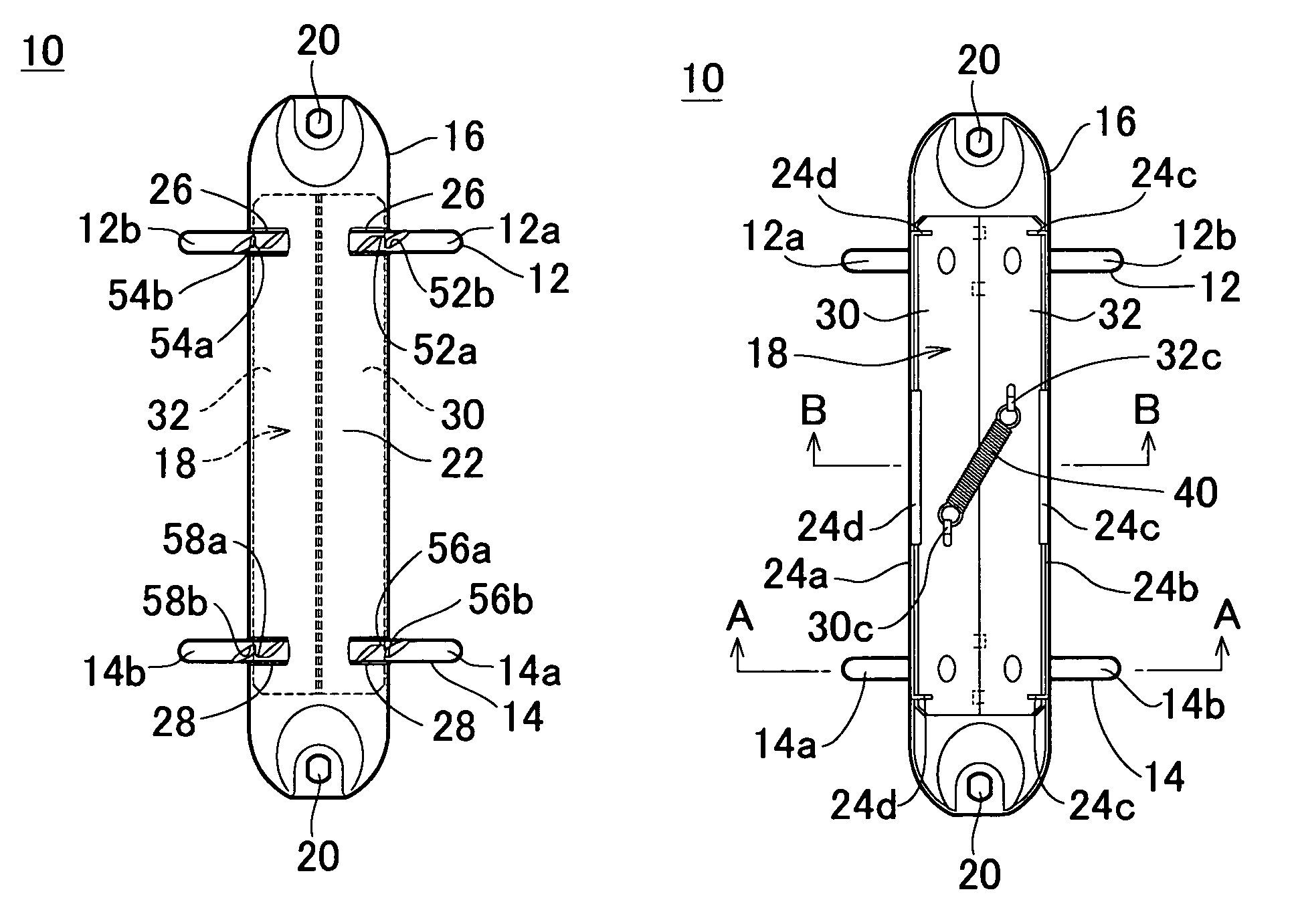
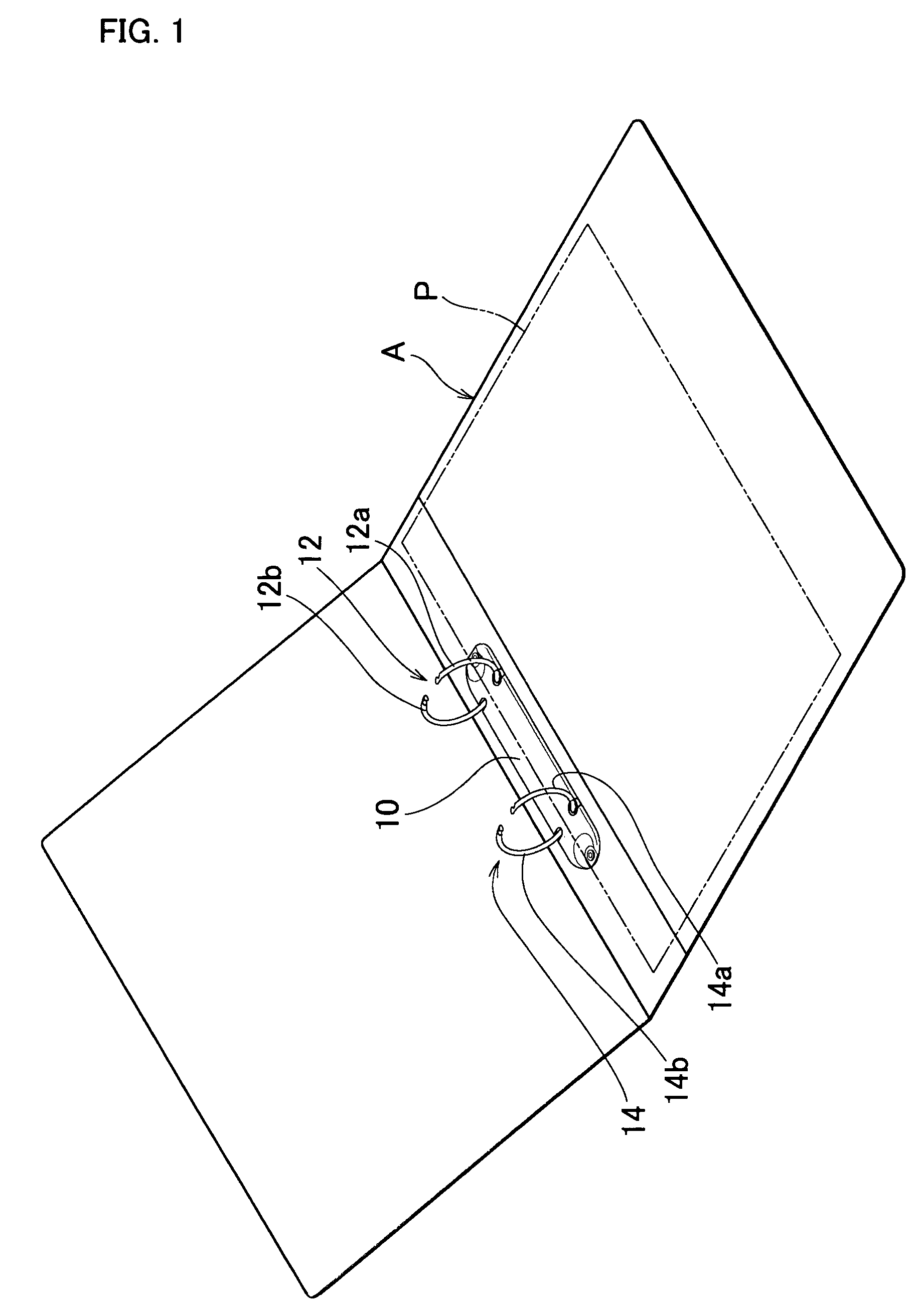
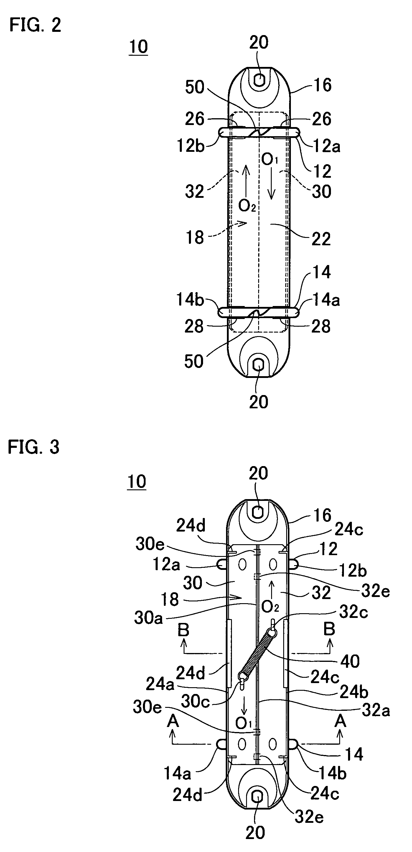
[0051]FIG. 1 is a perspective view showing an exemplary binding device according to a preferred embodiment of the present invention. FIG. 2 is a plan view showing the binding device in a closed state, FIG. 3 is a bottom view showing the binding device in a closed state, and FIGS. 4(A) and (B) are cross-sectional views showing the binding device in a closed state. FIG. 5 is a plan view showing the binding device in an opened state, FIG. 6 is a bottom view showing the binding device in an opened state, and FIGS. 7(A) and (B) are cross-sectional views showing the binding device in an opened state. FIG. 8 is a schematic plan view showing the vicinity of a latching portion of a binding ring in a closed state, and FIG. 9 is a schematic plan view showing the vicinity of the latching portion of a binding ring in an opened state. FIGS. 10 and 11 are schematic views respectively showing a structure of the binding device. FIG. 12 is a cross-sectional view showing a state where the binding devi...


PUM


Abstract

A binding device includes binding rings, a holding member having a length that enables the binding rings to be arranged at a distance from each other, and an operating member movably fixed inside the holding member such that the respective bases of the binding rings are secured onto a surface of the operating member at a distance to secure the binding rings to the holding member. In this binding device, the operating member includes a pair of operating pieces which move within the holding member in a longitudinal direction of the holding member. The base of one of the binding rings is secured to one of the operating piece, and the base of the other binding ring is secured to the other operating piece. The operating pieces are fixed to the holding member such that abutting edges thereof are maintained in an abutting state at a location spaced from an inner surface of the holding member when the binding rings are closed, and the abutting edges are maintained at a location closer to the inner surface of the holding member when the binding rings are opened, and an opening / closing member is provided for shifting the binding rings in an opening direction such that the operating pieces are moved in the longitudinal direction of the holding member within the holding member and are maintained at the location closer to the inner surface of the holding member when the binding rings are opened.

Description

BACKGROUND OF THE INVENTION[0001]1. Field of the Invention[0002]The present invention relates to a binding device, and in particular, for example, to a binding device used for a ring binder or file.[0003]2. Description of the Related Art[0004]A conventional binding device is configured such that an approximately annular binding ring is engaged at its center so as to be closed. For example, if the ring is manually opened or closed, a pair of approximately semicircular binding half rings which together define an approximately annular binding ring are pulled apart with fingers so as to be separated from each other, thereby opening the binding ring.[0005]When the approximately annular binding ring is opened with fingers, however, it is difficult to open the pair of approximately semicircular binding half rings defining the binding ring when a relatively large number of sheets of a document are bound.[0006]Therefore, for example, a ring file disclosed in Japanese Patent Laid-Open Publica...

Claims


Application Information

Patent Timeline
Patent Type & Authority Patents(United States)
IPC IPC(8): B42F13/00B42F13/22
CPCB42F13/22
Inventor TANAKA, KANJIARAI, HIROSHINAKANO, HIROSHI
Owner LIHIT LAB INC
Why Eureka
Try Eureka