
Stator for an electric machine

a technology for electric machines and stabilizers, which is applied in the direction of dynamo-electric machines, synchronous generators, electrical apparatus, etc., can solve the problems of increasing the space between, and achieve the effect of convenient installation and reliable holding

Inactive Publication Date: 2009-01-20
ZF FRIEDRICHSHAFEN AG
View PDF11 Cites 3 Cited by
  • Summary
  • Abstract
  • Description
  • Claims
  • Application Information

AI Technical Summary

Benefits of technology

The solution allows for a compact stator design by eliminating the need for axial extensions and provides a reliable, rapid installation method for the carrier element, ensuring secure attachment and efficient electrical connections.

Problems solved by technology

The spring tongues are thus pushed apart, which increases the size of the space between them.

Method used


Image

  • Stator for an electric machine
  • Stator for an electric machine

Examples


Embodiment Construction

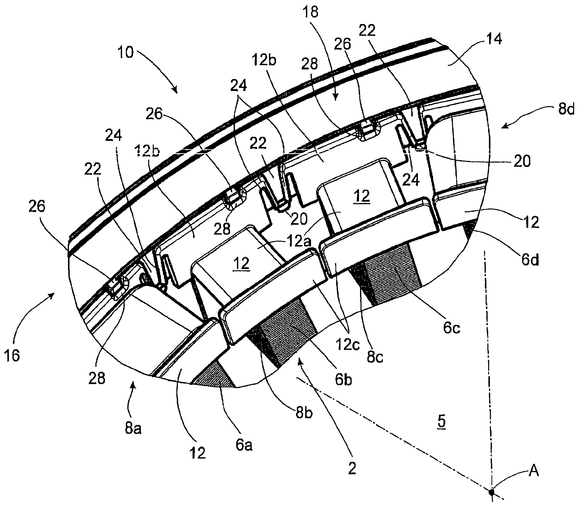
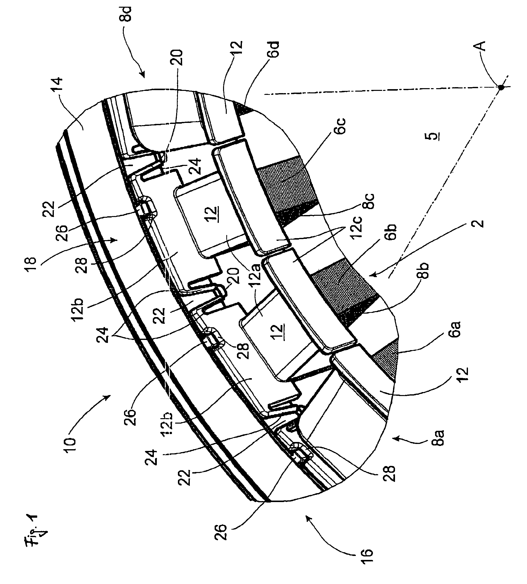
[0016]FIG. 1 is a schematic view, in perspective, looking in the direction proceeding radially outward from a radially inner position, of part of a stator 10 for an electric machine, the rest not being shown, with a ring-shaped stator yoke 2 consisting of a lamination pack of electrical steel sheet, which is covered for the most part by additional elements of the stator 10, as will be explained below. The stator 10 in question here is a synchronous electric machine of the internal rotor type, excited by permanent magnets, where the stator 10 shown has a cylindrical interior space 5, in which a rotor can be accommodated. In the known manner, the stator yoke 2 has a number of radially inward-pointing teeth 6a-d, distributed uniformly around the circumference, which carry the individual coils 8a-d. The coils 8a-d are wound separately in a preceding production step with the help of two winding bodies 12, consisting of insulating material, and then pushed over the teeth 6a-d of the stato...


PUM


Abstract

The stator for an electric machine includes a ring-shaped stator yoke, on which stator coils, formed on winding bodies and distributed uniformly around the circumference, are mounted. The coils are wired electrically together by a wiring arrangement, which has a ring-shaped carrier element designed to be attached to the stator to hold connecting conductors. The carrier element is mounted radially with respect to the winding elements. To ensure a simple and reliable mounting of the carrier element on the stator, it is proposed that the carrier element be held in place on the winding bodies by means of a latching connection so that it cannot move in the axial direction.

Description

BACKGROUND OF THE INVENTION[0001]The invention pertains to a stator for an electric machine. In particular, the invention pertains to the arrangement of a ring-shaped carrier element which holds the electrical connecting conductors used to wire the stator together and thus forms part of the arrangement for wiring the individual stator coils.[0002]Known stators for electric machines have a stator yoke with a certain number of stator teeth, which carry the electrical winding in the form of, for example, individual stator coils formed out of insulated wire. The two ends of each coil are assigned to individual phases, and the coils are wired together in a predetermined manner by means of a wiring arrangement, which includes common connecting conductors. In the case of a 3-phase machine, the stator has three phases and thus at least three connecting conductors, which are supplied with current at a phase offset of 120° from each other. The connecting conductors are connected to a switch b...

Claims


Application Information

Patent Timeline
Patent Type & Authority Patents(United States)
IPC IPC(8): H02K3/46
CPCH02K3/325H02K3/522
Inventor WELKE, KNUTZIMMER, MANFRED
Owner ZF FRIEDRICHSHAFEN AG
Learn More