High areal density tape head

a tape head and high density technology, applied in the direction of maintaining the head carrier alignment, the alignment of track following on the tape, instruments, etc., can solve the problems of track misregistration, track misregistration with the tape head, and requires sophisticated mechanics and skew compensation circuitry, so as to reduce the spacing of the tape track

Inactive Publication Date: 2009-01-20
INT BUSINESS MASCH CORP
View PDF17 Cites 45 Cited by
  • Summary
  • Abstract
  • Description
  • Claims
  • Application Information

AI Technical Summary

Benefits of technology

[0009]The foregoing problems are solved and an advance in the art is obtained by a tape head designed for transducing data on a magnetic recording tape that is subject to tape dimensional changes. The tape head includes two or more arrays of transducer elements having different transducer spacing distances corresponding to different track spacing distances to be transduced. One of the transducer arrays may be used for transducing the tape under nominal tape track spacing conditions. Another transducer array may be used for transducing the tape when the tape track spacing is reduced due to the tape shrinkage. Still another transducer array may be used for transducing the tape when the tape track spacing is enlarged due to tape expansion. Alternatively, the first transducer array can be used and the tape can be stretched longitudinally to reduce the tape track spacing to the nominal tape track spacing.

Problems solved by technology

Although the foregoing track writing techniques allow data to be densely packed on a tape, a continuing unresolved problem is track misregistration caused by tape dimensional changes between transducing (either reading or writing) operations.
These tape dimensional changes will widen or narrow the tape track spacing geometry, resulting in track misregistration with the tape head (whose gap spacing geometry is substantially unchanged).
Providing a head that is statically rotated to a nominal predetermined angle addresses the misregistration problem because small changes in rotation change the effective track pitch of the transducer array “E.” However, this solution requires sophisticated mechanics and skew compensation circuitry.
The track misregistration problem is exacerbated in conventional tape heads due to the relatively large gap spacing of the transducer array “E.” which is mandated to a large extent by the size of the transducers themselves.
Unfortunately, reducing track pitch using current thin film transducer fabrication techniques is not a trivial challenge due particularly to the size requirements of the write element structures.
Absent the use of alternative transducer designs that permit reductions in track pitch (as previously proposed by one of the applicants herein in commonly-owned patent application filings), or the use of complicated head rotation techniques as referred above, there is no conventional technique for dealing with the thermally induced track misregistration.

Method used


Image

  • High areal density tape head
  • High areal density tape head
  • High areal density tape head

Examples


Embodiment Construction

[0033]The invention will now be described by way of exemplary embodiments shown by the drawing figures (which are not necessarily to scale), in which like reference numerals indicate like elements in all of the several views.

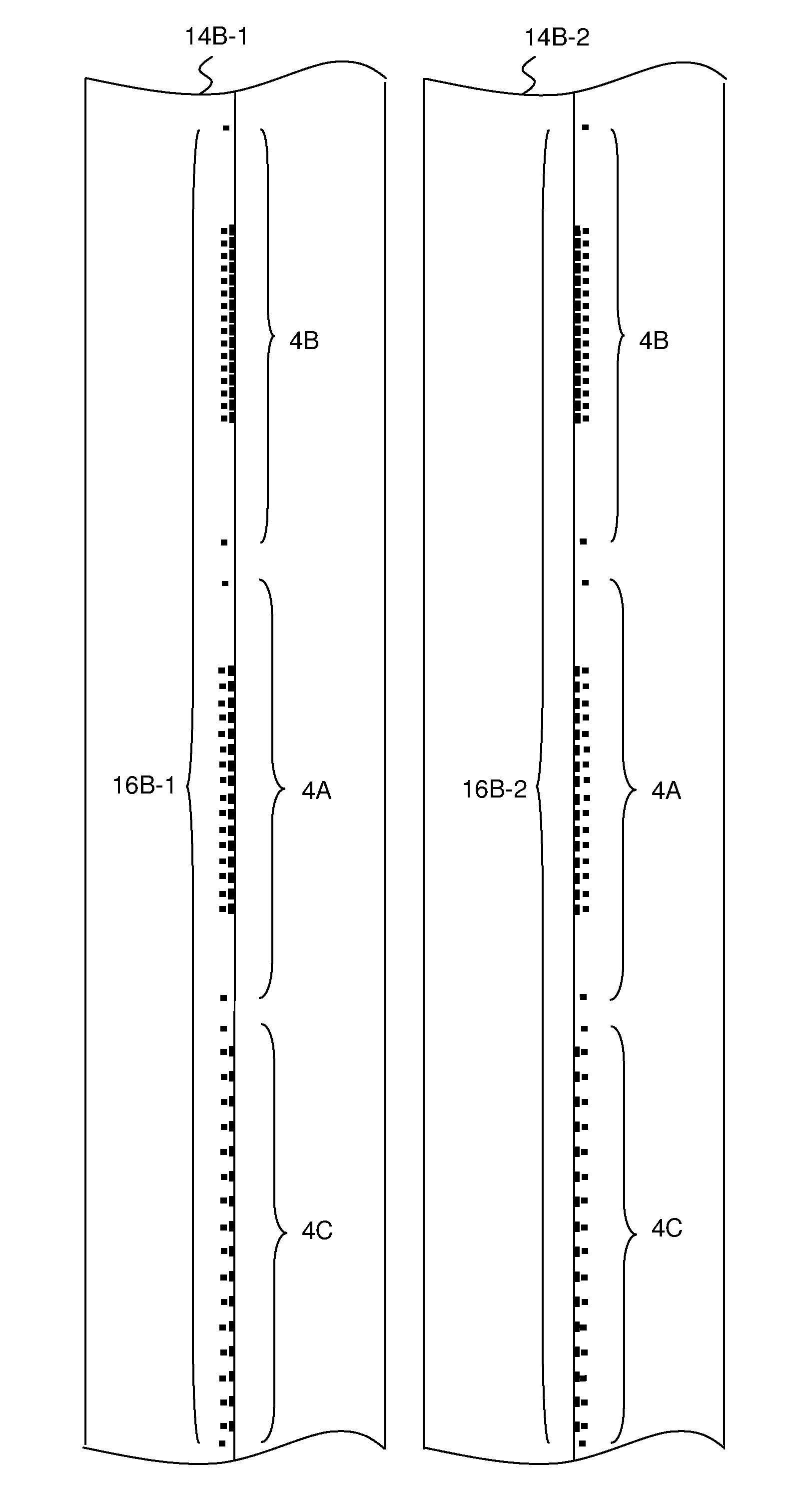
[0034]Turning now to FIG. 6, a tape head 2 is designed for transducing data on a magnetic recording tape that is subject to tape dimensional changes. The tape head includes two or more arrays of transducer elements having different transducer spacing distances (center-to-center pitch) corresponding to different track spacing distances (center-to-center pitch) to be transduced. One of the transducer arrays 4A has nominal transducer spacing and may be used for transducing the tape under nominal tape track spacing conditions. Another transducer array 4B has reduced transducer spacing and may be used for transducing the tape when the tape track spacing is reduced due to the tape shrinkage. Still another transducer array 4C has enlarged tape track spacing and may be ...


PUM

PropertyMeasurementUnit
lengthaaaaaaaaaa
lengthaaaaaaaaaa
lengthaaaaaaaaaa

Abstract

A tape head designed for transducing data on a magnetic recording tape that is subject to tape dimensional changes. The tape head includes two or more arrays of transducer elements having different transducer spacing distances corresponding to different track spacing distances to be transduced. One of the transducer arrays may be used for transducing the tape under nominal tape track spacing conditions. Another transducer array may be used for transducing the tape when the tape track spacing is reduced due to the tape shrinkage. Still another transducer array may be used for transducing the tape when the tape track spacing is enlarged due to tape expansion.

Description

BACKGROUND OF THE INVENTION[0001]1. Field of the Invention[0002]This invention relates to tape drive data storage systems. More particularly, the invention is directed to thin film tape heads for reading and writing data on magnetic recording tape.[0003]2. Description of the Prior Art[0004]Thin film tape heads for magnetic information storage systems (e.g., tape drives) have been constructed using thin film fabrication techniques that are similar to those used in the manufacture of disk drive transducers. In a typical tape head constructed for linear recording (i.e., with data tracks oriented in the direction of tape movement) there are two or more adjacently mounted transducer modules. Each module comprises a linear array of reader and / or writer transducer elements arranged in a cross-track direction that is perpendicular to the direction of tape movement. Each transducer element in a given transducer array is positioned to write or read a separate longitudinal track on the tape. T...

Claims


Application Information

Patent Timeline
Patent Type & Authority Patents(United States)
IPC IPC(8): G11B5/584
CPCG11B5/584
Inventor BISKEBORN, ROBERT G.IMAINO, WAYNE I.
Owner INT BUSINESS MASCH CORP
Why Eureka
Try Eureka