
GPS enabled cell phone with compass mode mapping function

a cell phone and compass technology, applied in the field of wireless communication, can solve the problems of limited storage of map segments used for navigational purposes, inability to provide more than minimal functionality of wireless terminals, and voluminous map information

Active Publication Date: 2009-01-20
AVAGO TECH INT SALES PTE LTD
View PDF11 Cites 21 Cited by
  • Summary
  • Abstract
  • Description
  • Claims
  • Application Information

AI Technical Summary

Problems solved by technology

Such map information is quite voluminous, often requiring many CDs to store.
Due to the limited storage capabilities of many handheld terminals, storage of map segments used for navigational purposes has been limited.
With such limitations, these wireless terminals were unable to provide more than minimal functionality.
Further, with limited mapping ability and communication functions, these devices provided only limited usefulness.

Method used


Image

  • GPS enabled cell phone with compass mode mapping function
  • GPS enabled cell phone with compass mode mapping function
  • GPS enabled cell phone with compass mode mapping function

Examples


Embodiment Construction

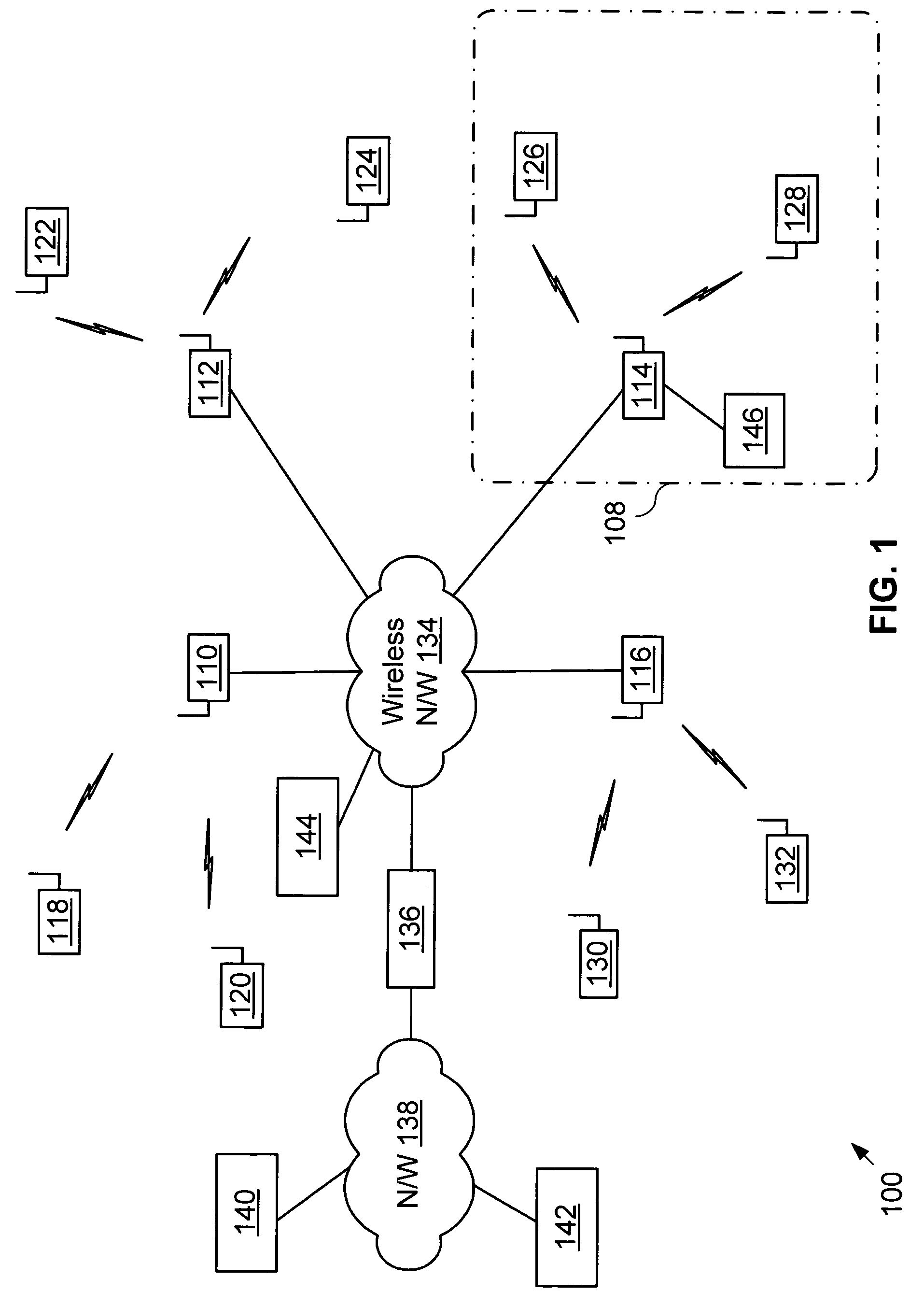
[0017]FIG. 1 is a system diagram illustrating a wireless communication system that operates according to the present invention. The wireless communication system 100 of FIG. 1 includes one or more servicing base stations and / or wireless access points (WAPs) 110, 112, 114, and 116. The reader should understand that the structure of FIG. 1 is used only to convey the principles of the present invention and is not intended to be a detailed description of a cellular wireless communication system, a Wireless Local Area Network (WLAN), a Wireless Wide Area Network (WWAN), or a Wireless Personal Area Network (WPAN).

[0018]As is shown, base station / WAP 110 supports wireless terminals 118 and 120 within a respective serving area, e.g., cell, sector, premises, area, etc. Likewise, base station / WAP 112 supports wireless terminals 122 and 124, base station / WAP 114 supports wireless terminals 126 and 128 within premises 108, and base station / WAP 116 supports wireless terminals 130 and 132. The bas...


PUM


Abstract

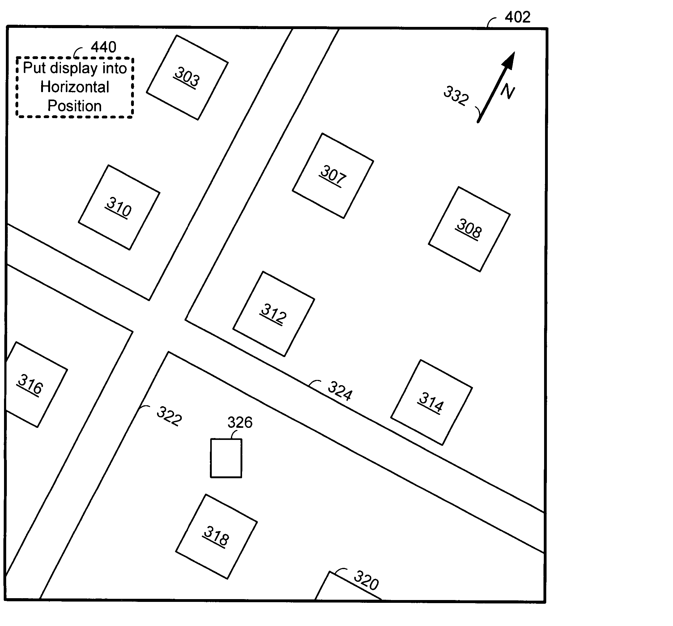
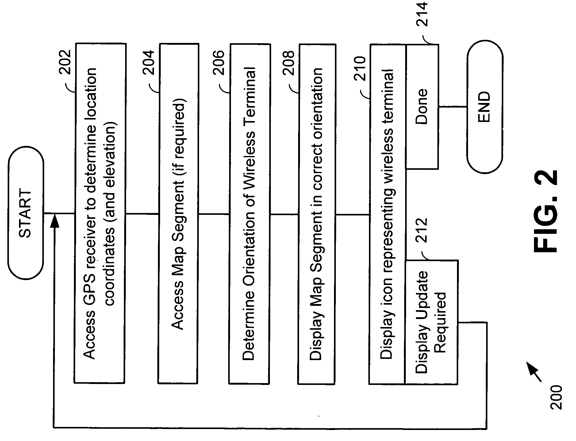
A wireless terminal displays its location and a map segment on a display of the wireless terminal. Operation commences with the wireless terminal accessing its GPS receiver to determine its location coordinates. Based upon its location coordinates, the wireless terminal accesses a map segment. The wireless terminal determines its orientation with respect to a reference direction. The wireless terminal displays the map segment on its display such that the map segment is displayed in a correct orientation with respect to mapped physical features. The wireless terminal displays an icon on its display that represents the wireless terminal. The icon is displayed on the map segment at a location corresponding to the location coordinates of the wireless terminal. The display of the wireless terminal orients the mapped physical features on the display so that they are oriented correctly with respect to the actual physical features.

Description

CROSS REFERENCE TO RELATED APPLICATION[0001]This application claims priority to U.S. Provisional Patent Application Ser. No. 60 / 647,089, filed Jan. 26, 2005, which is incorporated herein by reference for all purposes.BACKGROUND[0002]1. Field of the Invention[0003]The present invention relates generally to wireless communications; and more particularly to operations relating to the location / mobility of a wireless terminal.[0004]2. Background of the Invention[0005]Communication systems are well known. Communication systems include both wired communication systems and wireless communication systems. Wired communication systems include the Public Switched Telephone Network (PSTN), Wide Area Networks (WANs), Local Area Networks (LANs), and other networks that use wired or optical media for the transmission of data. Wireless communication systems include cellular telephone systems, satellite communication systems, Wireless Local Area Networks (WLANs), Wireless Personal Area Networks (WPAN...

Claims


Application Information

Patent Timeline
Patent Type & Authority Patents(United States)
IPC IPC(8): H04B1/38H04M1/00H04W4/02H04W4/029
CPCG01C21/20G09B29/106H04W4/02H04W4/029
Inventor KARAOGUZ, JEYHANBENNETT, JAMES D.
Owner AVAGO TECH INT SALES PTE LTD
Learn More