Orientation and navigation for a mobile device using inertial sensors

a mobile device and inertial sensor technology, applied in the field of visual navigation systems, can solve the problems of limited ability to modify the orientation of the map, limited capability of three-dimensional simulation, and disadvantages of current gps-based visualization interfaces, and achieve the effect of improving navigation and orientation

Inactive Publication Date: 2005-12-13
ROBERT BOSCH GMBH
View PDF24 Cites 192 Cited by
  • Summary
  • Abstract
  • Description
  • Claims
  • Application Information

AI Technical Summary

Benefits of technology

[0017]In response to certain signals received from the inertial sensor, the processor can activate or deactivate controls of the user interface. For example, abrupt movements of the mobile device conducted by the user, which cause generation of high frequency signals, can trigger the processor to activate or deactivate controls of the user interface, providing convenient manual control of the functionality of the mobile device.
[0018]According to a further aspect, the present invention provides a mobile device for enhanced navigation and orientation that includes a visualization interface and a sensor for detecting an attitude of the mobile device and generating corresponding signals that provide feedback for user control and for generating an image in the visualization interface that corresponds in viewpoint to the detected attitude of the mobile device.

Problems solved by technology

Current visual navigation interface systems (“visualization interfaces”) for mobile devices typically suffer from drawbacks in terms of their convenience of use and in the realism of the visual simulation which they provide.
This active input requires the use of a free hand, which can be inconvenient when the visualization interface is incorporated in a handheld device such as a Personal Digital Assistant (PDA), already occupying the use of one hand.
Even those visualization interfaces that are equipped with Global Positioning System (GPS) receivers and obtain location coordinates thereby, generally provide two-dimensional “map” views with only limited capability to modify the map orientation.
Additionally, current GPS-based visualization interfaces have only limited capabilities for three-dimensional simulation because the GPS reception system usually does not provide attitude (angular orientation) information.

Method used


Image

  • Orientation and navigation for a mobile device using inertial sensors
  • Orientation and navigation for a mobile device using inertial sensors
  • Orientation and navigation for a mobile device using inertial sensors

Examples


first embodiment

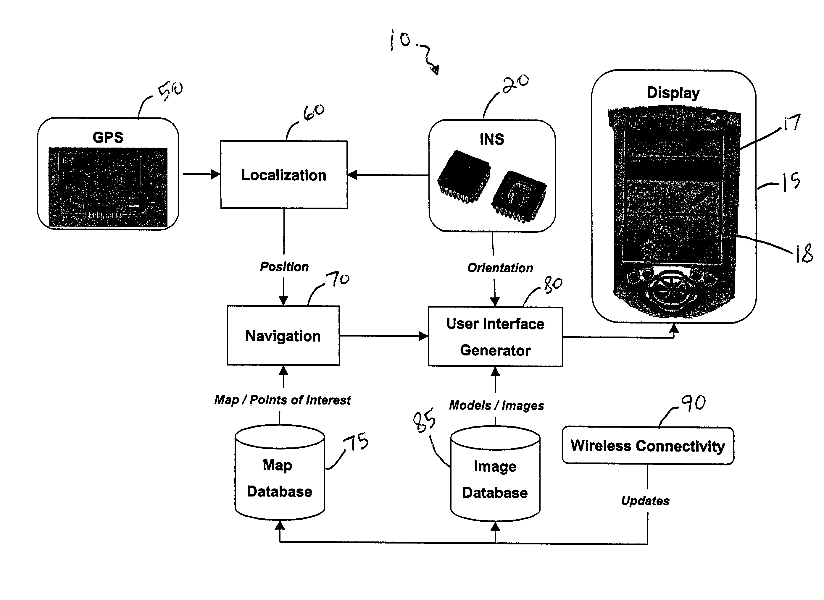
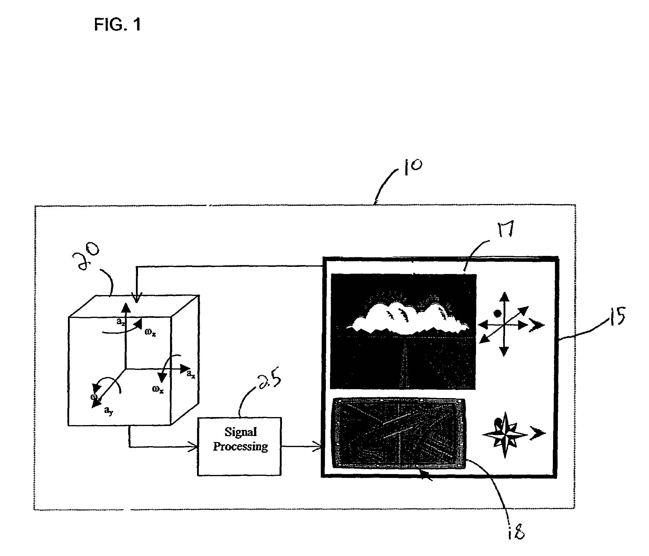
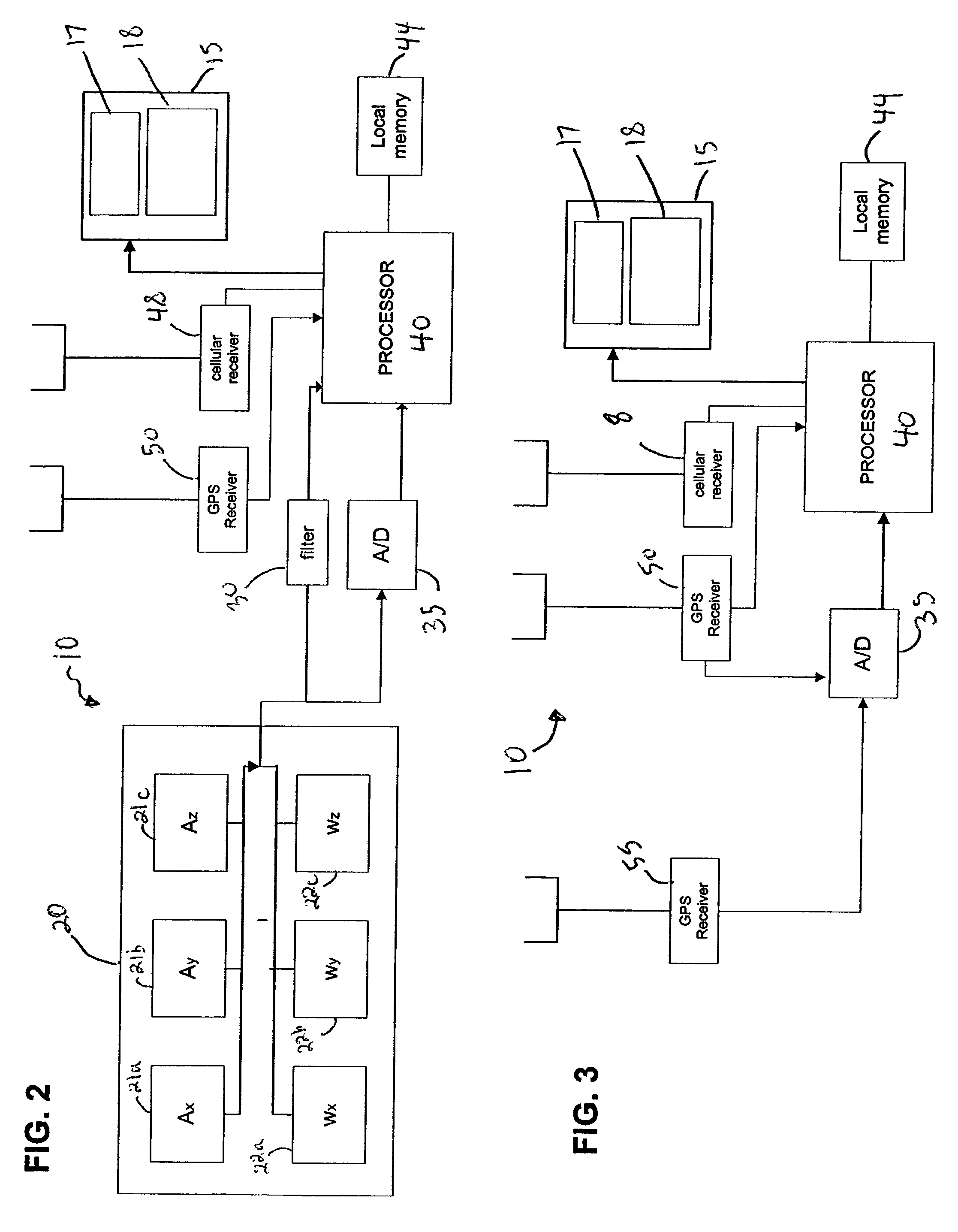
[0035]Such navigation is accomplished using sensors, depicted in block 20, which provide signals for estimation of the movement of the mobile device. As described below, the sensors include inertial acceleration and rotational velocity sensors that provide for estimation of both the relative translation and the rotation of the mobile device (with respect to a reference frame) in addition to one or more GPS receivers for estimating either absolute position alone (using one GPS receiver) or both absolute position and orientation (using two or more GPS receivers). According to another embodiment, the sensors include multiple GPS receivers for estimating absolute position and orientation in three dimensions without use of inertial sensors. The inertial sensors provide direct signals that may be used for certain types of user interaction such as for changing the state of a graphical user interface control. Thus, if the user abruptly moves or twists the mobile device, causing a sudden in...

second embodiment

[0043]FIG. 3 depicts a schematic view of the mobile device according to the present invention including multiple GPS receivers. As shown in FIG. 3, mobile device 10 includes a first GPS receiver 50 and a second GPS receiver 55. The processor 40 uses the input from the first GPS receiver 50 to calculate a coordinate position in terms of latitude, longitude, and altitude estimated by triangulation using differential times of receipt of GPS signals transmitted from a plurality of GPS satellites. Using the input from the second GPS receiver 55, located some distance from the first GPS receiver 50 on the mobile device 10, the processor can estimate the attitude of the mobile device by comparing the relative differences between the timing of GPS signals received by the respective GPS receivers 50, 55. Thus, according to this embodiment, location and attitude are estimated using the GPS system without reliance on inertial sensors.

[0044]FIG. 4 depicts a software model of the mobile device 1...


PUM


Abstract

A mobile device for enhanced navigation and orientation including a visualization interface, a first sensor for providing signals indicative of a movement of the mobile device, a second sensor for providing further signals indicative of a movement of the mobile device, and a processor receiving signals from the first and second sensors, calculating a position and an orientation of the mobile device from the received signals, and generating a real time simulation of an environment via the visualization interface based on the position and orientation of the mobile device. According to an embodiment, the first and second sensors are implemented as an inertial sensor and a GPS receiver, respectively.

Description

FIELD OF THE INVENTION[0001]The present invention relates to visual navigation systems, and in particular, but without limitation, relates to a system and method for providing enhanced user orientation and navigation for a mobile device using multiple sensors.BACKGROUND INFORMATION[0002]Current visual navigation interface systems (“visualization interfaces”) for mobile devices typically suffer from drawbacks in terms of their convenience of use and in the realism of the visual simulation which they provide. Visualization interfaces for mobile devices usually require active user input to provide an orientation for visualization. The user may provide the input via an auxiliary device such as a mouse, a keypad, or a touch-screen cursor. In this case, if a user wishes to obtain visual information corresponding to a particular viewing orientation, he or she may be required to point a cursor or mouse in the selected direction. This active input requires the use of a free hand, which can b...

Claims


Application Information

Patent Timeline
Patent Type & Authority Patents(United States)
IPC IPC(8): G09B29/00G01C21/00G01C21/04G01C21/10G01C21/16G01C21/20G01C21/28G01C21/36G01S5/14G01S19/49G01S19/53G06F15/00G06T19/00G08G1/0969G08G3/00G08G5/00G09B29/10H04L29/06
CPCG01C21/206G01C21/3647G01S19/49G01S19/53
Inventor DIETRICH, ARNESCHMIDT, HAUKEHATHOUT, JEAN-PIERRE
Owner ROBERT BOSCH GMBH
Why Eureka
Try Eureka