Monitoring electrical assets for fault and efficiency correction

a technology of electrical assets and efficiency correction, applied in short-circuit testing, coupling device connections, instruments, etc., can solve problems such as inability to pin-point the source of faults, identify the probable cause of faults, identify the chain of events leading to faults, and inaccuracy of existing electricity meters

Active Publication Date: 2007-03-15
ACLARA TECH LLC
View PDF24 Cites 199 Cited by
  • Summary
  • Abstract
  • Description
  • Claims
  • Application Information

AI Technical Summary

Benefits of technology

[0007] The present invention is embodied in an apparatus for monitoring an electrical asset in an electrical infrastructure. The apparatus may include a sensor coupled to the electrical asset for obtaining data corresponding to at least one of a voltage, current, and phase angle waveforms, a globally synchronized timer for time-stamping the data with a globally synchronized time, a mesh network radio for communicating at least one gateway and for relaying communications between one or more other electrical asset monitors and the at least one gateway, and a power supply for extracting and storing energy from the electrical asset and supplying power to at least the sensor, the timer, and the radio.

Problems solved by technology

These existing monitoring systems, however, are unable to pin-point the source of a fault, identify the probable cause of the fault, or identify the chain of events leading to the fault.
A further problem faced by the utilities includes theft and inaccuracy in existing electricity meters, whereby customers are either consistently under-billed or over-billed due to inaccurate usage metering.
This presents an additional cost to utilities, however, as they incur overhead associated with hiring workers to drive around and collect meter and sensor readings, making such an implementation undesirably cost-prohibitive.

Method used


Image

  • Monitoring electrical assets for fault and efficiency correction
  • Monitoring electrical assets for fault and efficiency correction
  • Monitoring electrical assets for fault and efficiency correction

Examples


Embodiment Construction

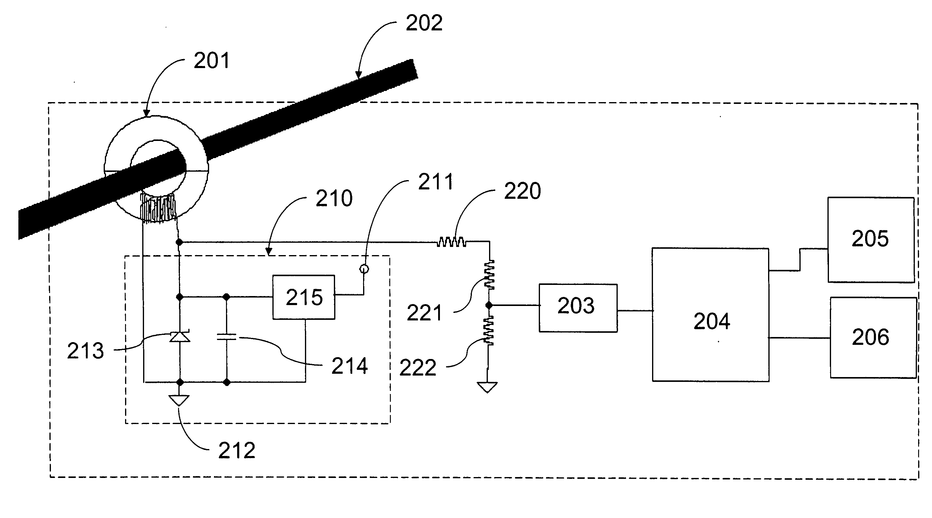
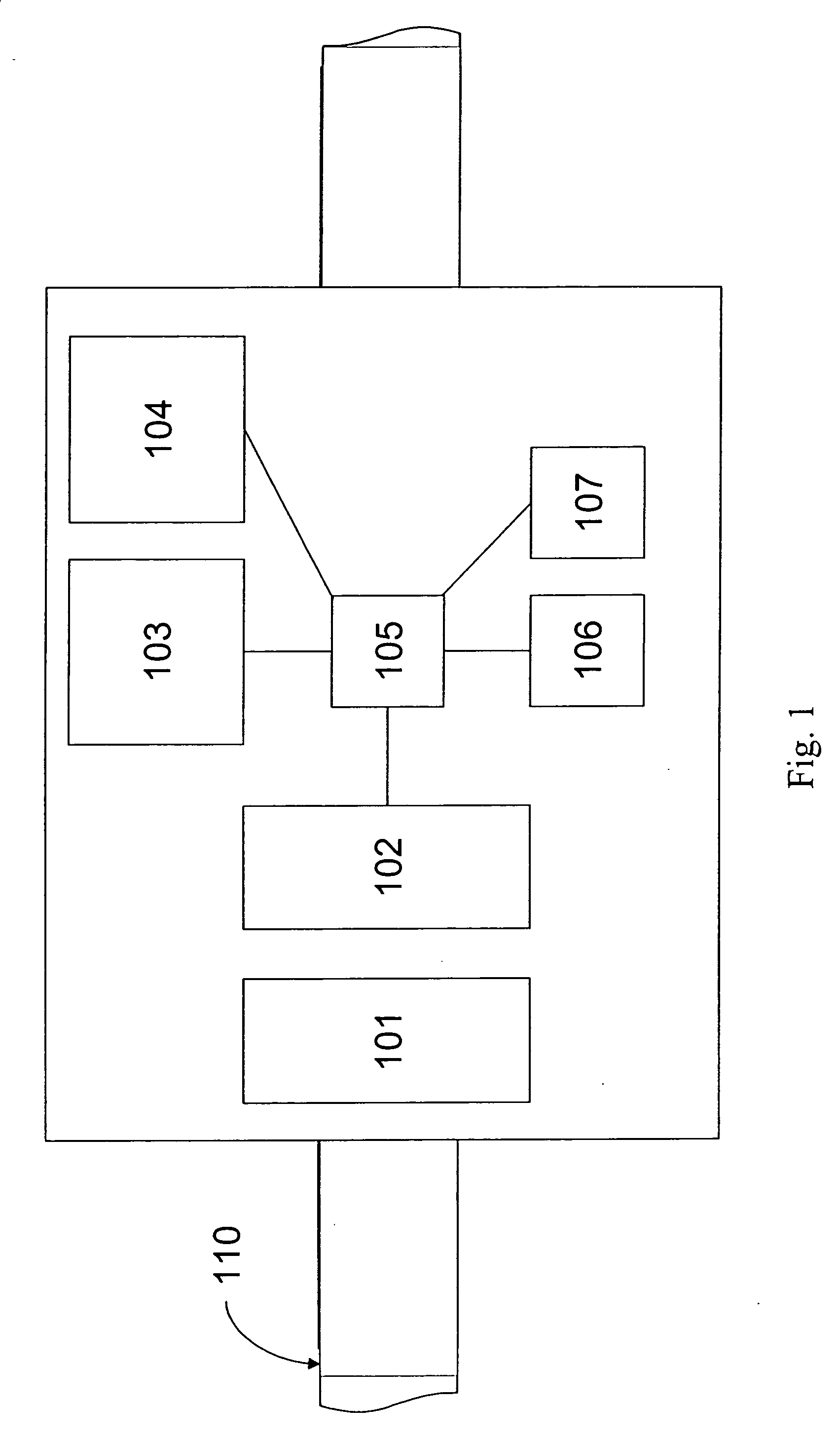
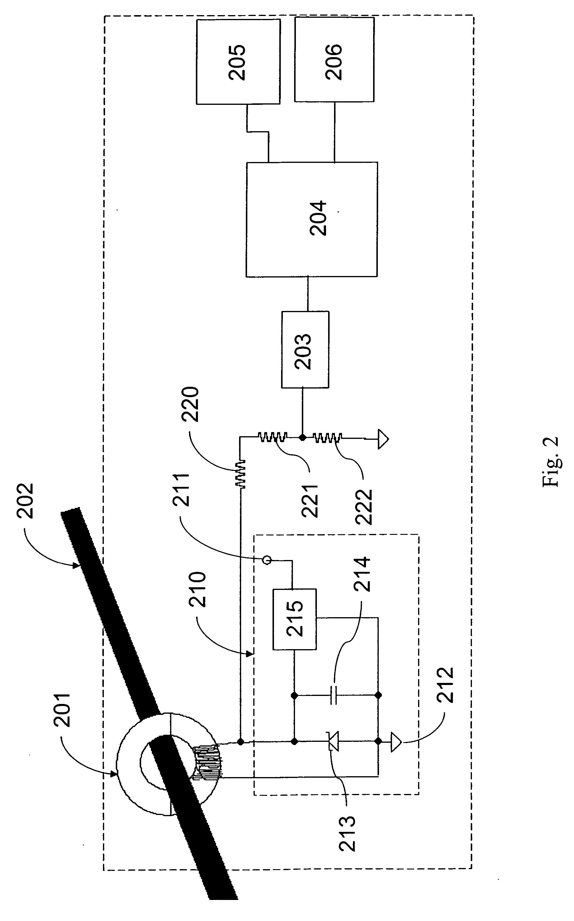
[0020] The present invention is embodied in an apparatus, system, and method of monitoring a plurality of electrical assets that comprise an electricity distribution infrastructure. The electric assets being monitored may include power lines, cables, circuit breakers, switches, and transformers, for example. Monitoring activities are overseen by a central command center that obtains sensor data from multiple gateways. Each gateway collects data from a plurality of remotely located sensors that are coupled to respective ones of the electrical assets for obtaining data on the operating condition of the electrical assets. Data from any given sensor is routed to a gateway via a mesh network, where the data is multi-hopped from sensor-to-sensor according to an efficient communication path to the gateway. The gateway then re-routes the data from the mesh network, which is a tier-2 network, to the central command center via a tier-1 network (e.g., radio link, fiber optic link, the Internet...


PUM


Abstract

A system and method of monitoring a plurality of electrical assets comprise an electricity distribution infrastructure, including a plurality of electrical asset sensors coupled to the electrical assets for monitoring an operating condition of the electrical assets as well as any fault conditions. The sensors may include a current transformer for obtaining a current waveform, a GPS receiver for applying a synchronized time-stamp to the waveform data, and a mesh network radio for transmitting the time-stamped waveform data. Data from the plurality of sensors may be encrypted and transmitted over a mesh network to one or more gateways that are in communication with a central command processor. In response to an abnormal operating condition of any electrical asset, the central command processor may determine a probable fault location, a probable fault type, and a fault response.

Description

[0001] This Application claims benefit of priority from U.S. Provisional Application No. 60 / 716,413 filed Sep. 13, 2005, the contents of which are incorporated herein by reference.TECHNICAL FIELD [0002] The present invention relates generally to monitoring an electrical infrastructure and, more particularly, to locating and identifying disturbances and determining status of electrical assets in an electrical infrastructure. BACKGROUND OF THE INVENTION [0003] Based, in part, on the recent deregulation of the electrical supply market, increased competition amongst electricity providers has prompted the need for increased efficiency in electricity distribution as well as increased quality of service. In the event of a fault condition, for example, there is a need for rapid determination of the fault location and fault type so that work crews may be dispatched for rapid response to a fault or outage. Within dense urban areas, in particular, there is a need for precise power distribution...

Claims


Application Information

Patent Timeline
Patent Type & Authority Applications(United States)
IPC IPC(8): H04Q5/22H01R33/00G01R31/50
CPCG01R19/2513G01R31/025H02H7/28G01R31/088G01R31/086G01R31/52G01R31/50
Inventor ROCKWELL, DANIEL
Owner ACLARA TECH LLC
Why Eureka
Try Eureka