High temperature steam valve and steam turbine plant

a high-temperature steam valve and steam turbine technology, which is applied in steam engine plants, machines/engines, mechanical equipment, etc., can solve the problems of high-temperature steam existence, valve rod creep deformation, and severe for the constituent materials of steam valves

Active Publication Date: 2009-01-27
KK TOSHIBA
View PDF12 Cites 16 Cited by
  • Summary
  • Abstract
  • Description
  • Claims
  • Application Information

AI Technical Summary

Benefits of technology

[0010]The present invention has been invented in view of the shortcomings of the conventional technologies described above. An object of the present invention is to provide a high temperature steam valve that can appropriately maintain the sliding gap between the valve rod and the bush for a long time by preventing or suppressing deposition of oxide scale upon cooling appropriately the sliding portion between the valve rod and the bush disposed at the valve-rod penetrating portion of the valve casing. Another object of the present invention is to provide a steam turbine plant employing such a high temperature steam valve.

Problems solved by technology

Although raising the steam temperature is welcome for improving the thermal efficiency of the steam turbine system, it is very severe for the constituent materials of the steam valve.
That is to say, the valve rod gets creep deformation, and oxidized scale which inhibits smooth sliding may deposit on the sliding portion between the valve rod and the bush, and moreover may stick the sliding portion between the valve rod and the bush with a high temperature steam existence.
However, in the technology described in the above-mentioned Japanese Utility Model Application Publication Sho 57-145879, only the valve rod can be cooled, and cooling the sliding portion between the valve rod and the bush is not taken into consideration.
Consequently, it is insufficient for the measure to prevent oxidized scale from depositing on the sliding portion.
As a result, the technologies described in Japanese Utility Model Application Publication Sho 61-14276 and Japanese Patent Application Publication Hei 8-93407 cannot prevent oxidized scale from depositing at a higher temperature steam even if anti-oxidized layers are provided.
Furthermore, because the technology described in Japanese Patent Application Publication 2004-19784 has the structure cooling the shaft seal part rather than the bearing member rotatably supporting the valve rod, heat is transferred from the valve inside to the bearing member i.e. the valve rod sliding portion via the valve rod, and thereby the rod sliding portion cannot be cooled sufficiently.
In consequence, the technology described in Japanese Patent Application Publication 2004-19784 also is not sufficient for the measure to prevent oxidized scale from depositing on the valve rod sliding portion which supports rotation of the valve rod.
As a result, the valve rod and others are obliged to be replaced because the sliding gap between the bush and the valve rod cannot be appropriately maintained for a long time.

Method used


Image

  • High temperature steam valve and steam turbine plant
  • High temperature steam valve and steam turbine plant
  • High temperature steam valve and steam turbine plant

Examples


first embodiment

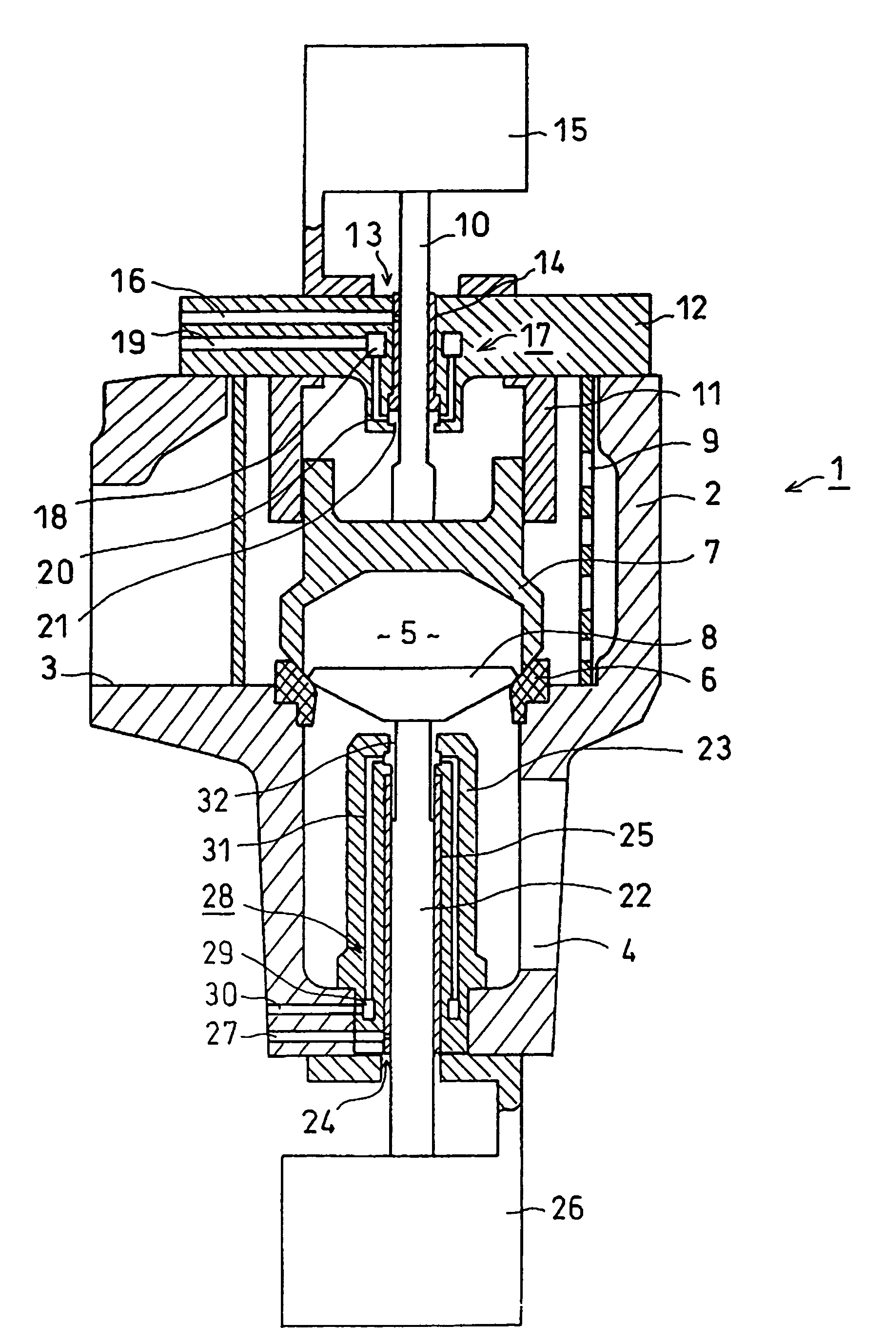
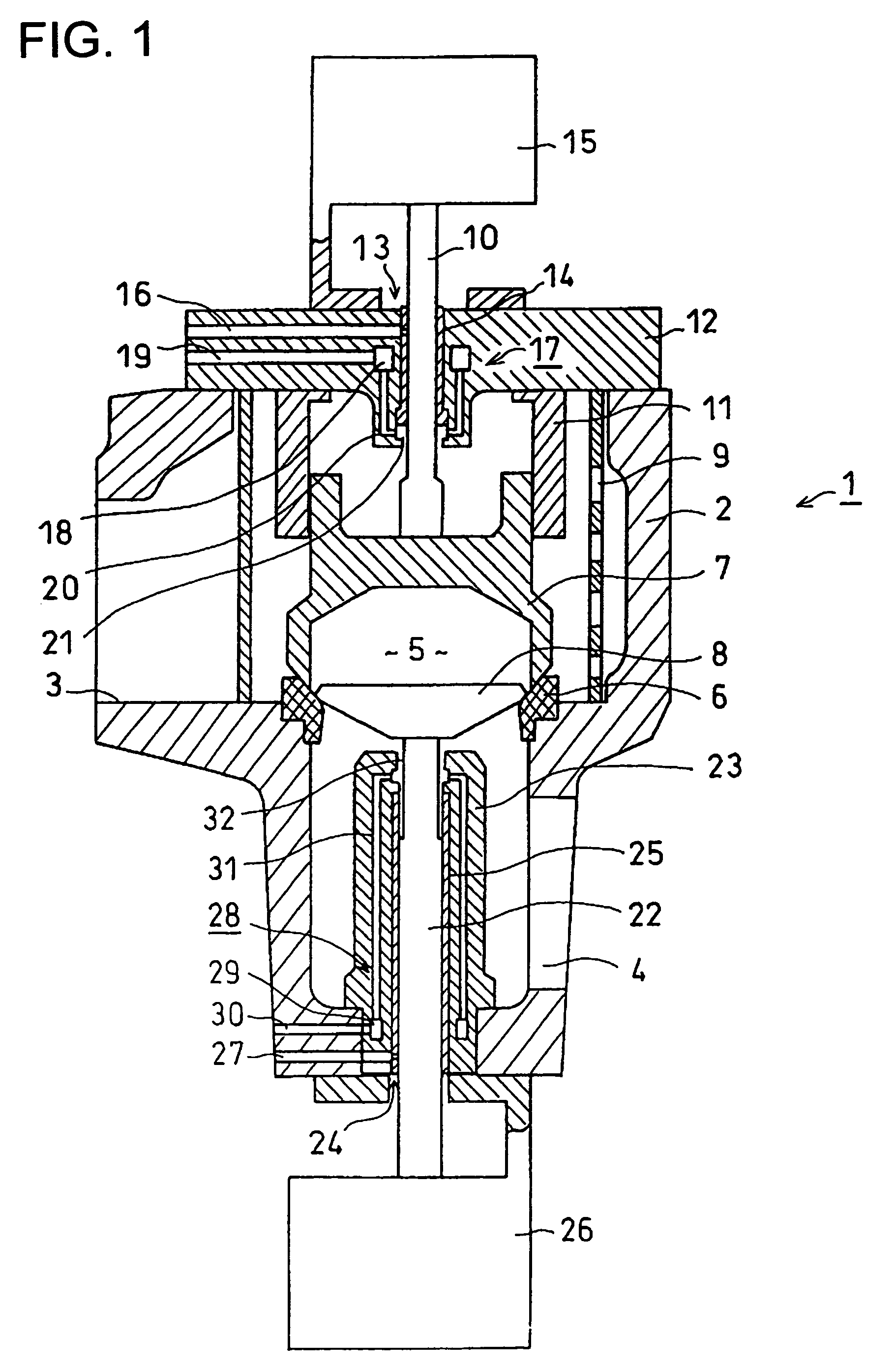
[0021]FIG. 1 is a vertical cross sectional view of the embodiment in which the present invention is applied to the composite-type reheat high temperature steam valve.

[0022]In FIG. 1, the fundamental structure of the composite-type reheat high temperature steam valve will be explained first. Numeral “1” represents the entire composite-type reheat high temperature steam valve. Numeral “2” represents the valve casing where a main steam inlet portion 3 on the left side as shown in the figure and a main steam outlet portion 4 on the opposite right bottom as shown in the figure are provided. A valve seat 6 is placed in a valve chest 5 formed between the main steam inlet portion 3 and the main steam outlet portion 4. A first valve element 7 and a second valve element 8 are driven to rise or descend toward the valve seat 6 from the bottom or the top of the figure. Numeral “9” represents a cylindrical strainer for eliminating dusts in the main steam.

[0023]The first valve element 7 has a near...

second embodiment

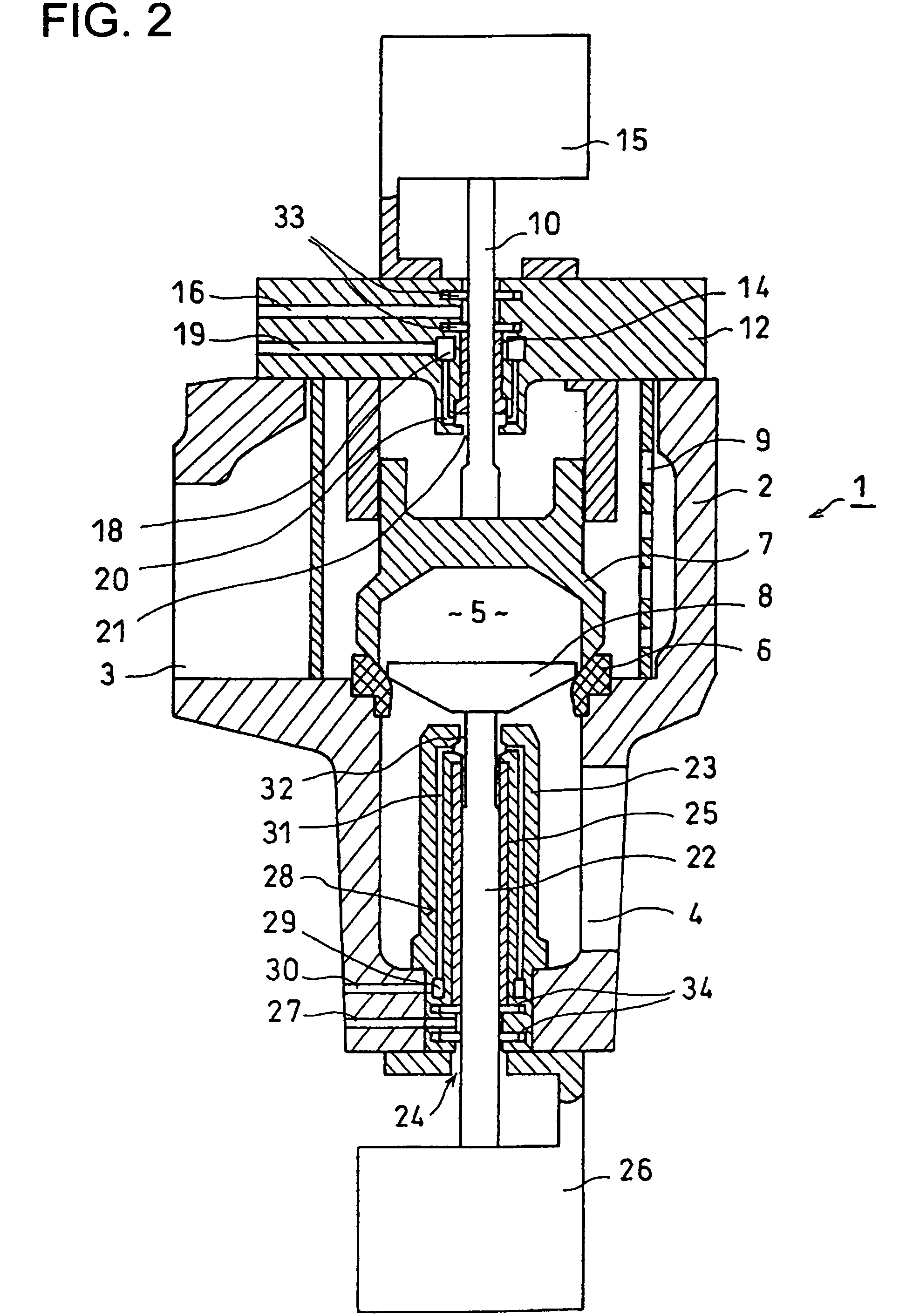
[0035]The second embodiment of the present invention is now explained referring to FIGS. 2, 4 and 5. This embodiment is also applied, like the first embodiment, to the composite-type reheat high temperature steam valve, so that each part corresponding to the FIG. 1 is denoted by the same numeral and explanation thereof will be appropriately omitted.

[0036]In FIG. 2, the main aspect of the second embodiment is that two piston rings 33 and two piston rings 34 are positioned. The openings of the steam vent holes 16 and 27 facing the peripheries of the valve rods 10 and 22, respectively, are positioned between the piston rings 33 and between the piston rings 34, respectively. The bushes 14, 25 are split into plural pieces. The other structures are the same as FIG. 1 mentioned above.

[0037]In the case of the second embodiment, the bush 14 does not fully penetrate the valve lid 12 but is mounted up to approximately the middle portion of the valve lid 12 in the thickness direction thereof fr...

third embodiment

[0042]Referring to FIGS. 3, 4 and 5, the third embodiment of the present invention is now explained. This embodiment shows an example applied to a main steam stop valve. In FIG. 3, the main steam stop valve 100 of the third embodiment has one valve element, so that the valve-rod penetrating portion 13 shown in FIG. 1 is not provided in the valve lid 12. Only the valve-rod penetrating portion 24 is provided at the bottom of the valve casing 2. The valve casing 2 of this embodiment is provided with the main steam inlet portion 3 on the left side of the figure and the main steam outlet portion 4 at the opposite bottom portion thereof on the right side of the figure. The valve seat 6 and the valve element 8 are located in the valve chest 5 formed between the main steam inlet portion 3 and the main steam outlet portion 4. The valve element is driven from the bottom side of the figure toward the valve seat 6 so that it can touch and detach the valve seat 6. Movement of the valve element 8...


PUM


Abstract

A high temperature steam valve has a valve casing including a main steam inlet, a main steam outlet and a valve chest. The high temperature steam valve also has a valve seat positioned in the valve chest, a valve element facing the valve seat, and a valve rod slidably penetrating the valve casing to drive the valve element. A cooling steam hole is provided to surround a valve-rod penetrating portion of the valve casing. Cooling steam can be poured into the cooling steam hole from outside through a cooling steam inlet hole and steam having finished heat exchange can be exhausted from a cooling steam outlet hole into the valve chest. The sliding portion between the valve rod provided in the valve-rod penetrating portion of the valve casing and bush is cooled to prevent oxidized scale from depositing on the sliding portion.

Description

CROSS-REFERENCE TO RELATED APPLICATIONS[0001]This application is based upon and claims the benefit of priority from the prior Japanese Patent Application No. 2004-260587, filed on Sep. 8, 2004; the entire content of which is incorporated herein by reference.BACKGROUND OF THE INVENTION[0002]The present invention is generally related to a high temperature steam valve, and more particularly to a high temperature steam valve employing a cooling mechanism to cool valve constituent elements. The present invention is also related to a steam turbine plant having a high temperature steam valve.[0003]Recently, it is required that steam turbines of thermal electric power plants be more effective in the light of the environmental problems, so that the steam temperature tends to be raised higher. The steam condition now adopted widely is of about 169 kg / cm2 and 566 degrees Celsius, or of about 246 kg / cm2 and 566 degrees Celsius as shown in Japanese Patent Application Publication Hei 7-247806, th...

Claims


Application Information

Patent Timeline
Patent Type & Authority Patents(United States)
IPC IPC(8): F01K13/00
CPCF16K49/005
Inventor FUKUDA, MASAFUMIHOSAKA, HIDEOOOISHI, TSUTOMU
Owner KK TOSHIBA
Why Eureka
Try Eureka