Gas turbine combustor

a combustor and gas turbine technology, applied in the direction of machines/engines, mechanical equipment, light and heating equipment, etc., can solve the problems of shortening the life, time and energy required for maintenance, and unable to carry out stable operation, so as to improve the reliability of the combustor, the effect of suppressing the oscillating combustion

Inactive Publication Date: 2006-04-25
MITSUBISHI HITACHIPOWER SYST LTD
View PDF11 Cites 19 Cited by
  • Summary
  • Abstract
  • Description
  • Claims
  • Application Information

AI Technical Summary

Benefits of technology

[0012]In the above-mentioned combustor, since the cooling-air-layer forming ring is provided between the liner of the combustion chamber and the fuel nozzle block, even when the fuel nozzle block deforms due to thermal expansion, a certain gap for forming the cooling-air layer can be maintained. Therefore, stable operation becomes possible, thereby improving the reliability of the combustor. Further, since the cooling-air-layer forming ring is protected from the high temperature combustion gas by the fuel nozzle block, the cooling-air-layer forming ring does not deform. Therefore, the gap formed between the cooling-air-layer forming ring and the liner of the combustion chamber is always kept at a certain interval, and hence even when the fuel nozzle block deforms during operation, the cooling-air layer is formed uniformly. As a result, the liner of the combustion chamber can be cooled stably, regardless of the operation time and operation condition of the gas turbine, and oscillating combustion can be suppressed.

Problems solved by technology

Conventionally, there is a problem in that combustion becomes unstable due to the oscillating combustion, and hence stable operation cannot be carried out.
Further, there is another problem in that when combustion occurs near the wall surface of the liner of the combustion chamber, the liner of the combustion chamber is overheated, thereby shortening the life thereof.
When the life of the liner of the combustion chamber becomes short, repair and replacement are required frequently, and hence time and energy are required for maintenance.

Method used


Image

  • Gas turbine combustor
  • Gas turbine combustor
  • Gas turbine combustor

Examples


second embodiment

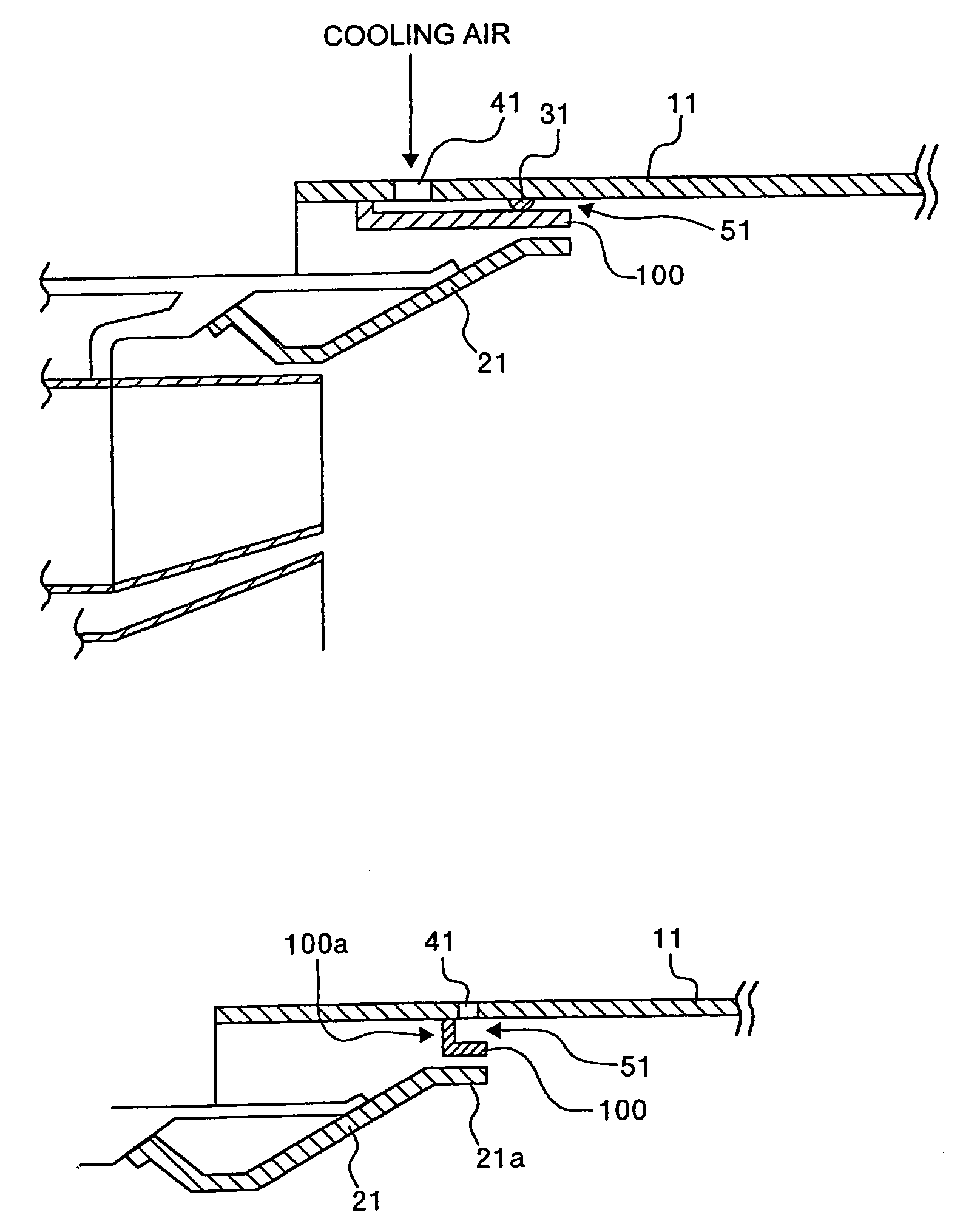
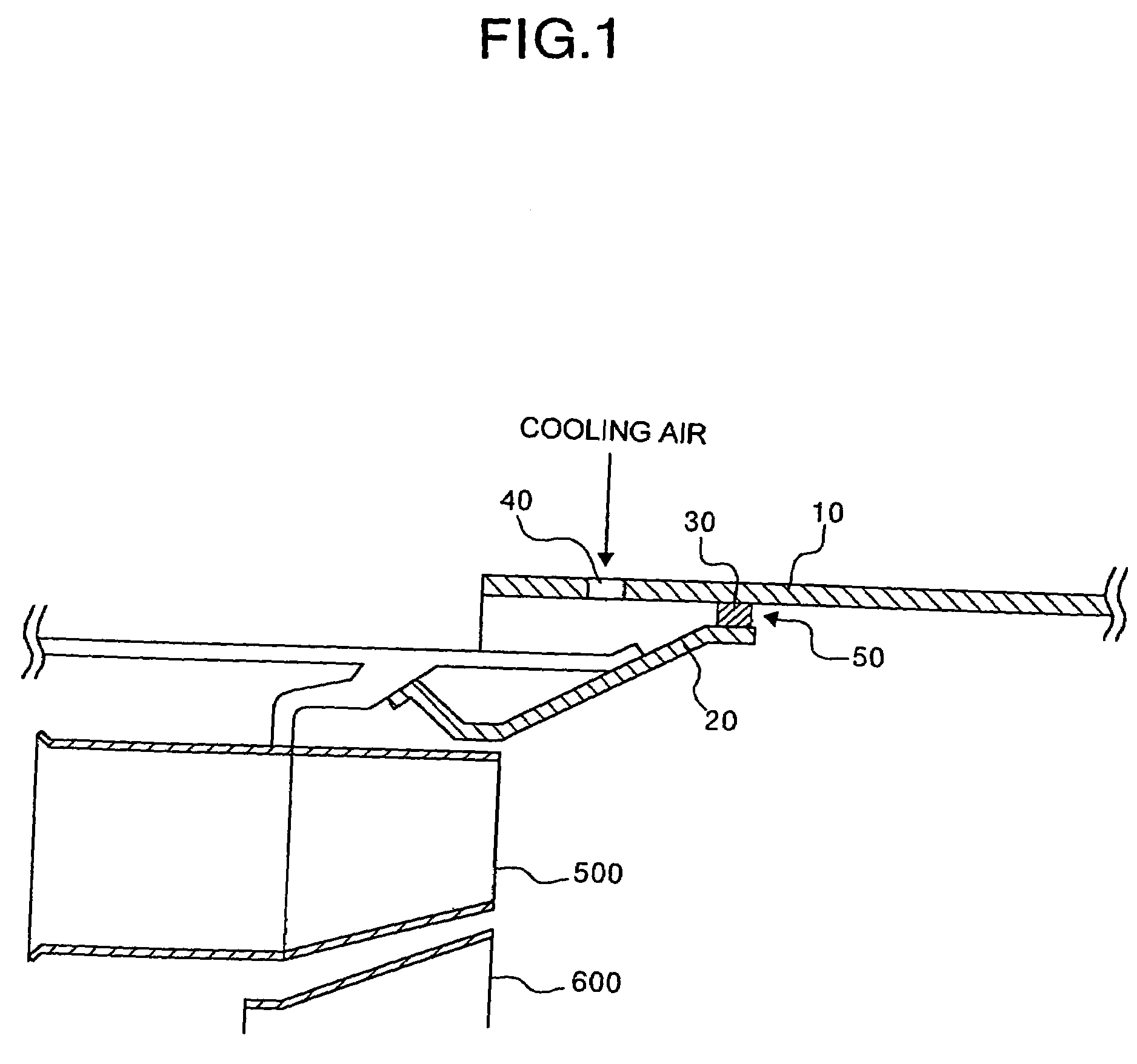
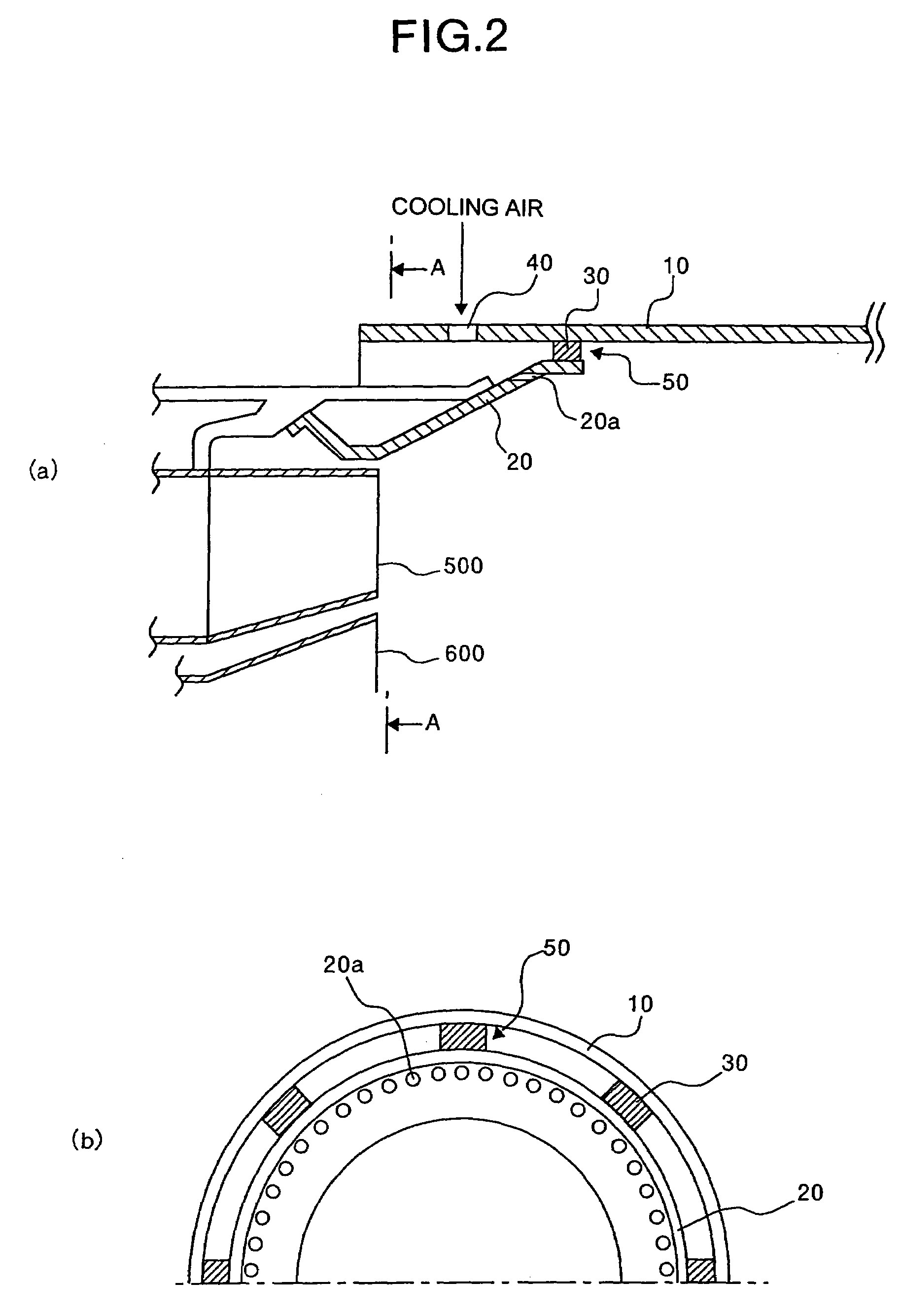
[0022]In the combustor according to the first embodiment, when the fuel nozzle block moves radially due to some reasons during the operation, the size of the gap formed between the inner surface of the combustor and the fuel nozzle block becomes nonuniform. As a result, the thickness of the cooling-air layer formed on the inner surface of the combustor becomes also nonuniform, and hence cooling of the inner surface may be insufficient.

[0023]When the nozzle block thermally expands, a radial deformation is restricted at portions where the spacers exist. Therefore, the deforming behavior changes between the portions where the spacers exist and the portions where the spacers do not exist, and hence the shape of the nozzle block as seen from the front becomes a flower shape (FIG. 3(a)). When the nozzle block deforms in such a shape, the interval of the gaps formed between the inner surface of the combustor and the fuel nozzle block becomes nonuniform, and the cooling-air layer formed on ...


PUM


Abstract

A combustor for a gas turbine has an arrangement to form a layer of cooling-air on an inner surface of a liner of a combustion chamber. This layer of the cooling air extends from a fuel nozzle block of the combustor toward a downstream side with respect to the liner.

Description

TECHNICAL FIELD[0001]The present invention relates to a combustor for a gas turbine, and more specifically, relates to a combustor that can stably cool its walls, regardless of the operation time and operation condition.BACKGROUND ART[0002]A premixed combustion method is used in the present day combustors a from a standpoint of environmental protection, because, the premixed combustion method achieves a reduction of thermal NOx. The premixed combustion method includes premixing a fuel and excessive air and burning the fuel. In the premixed combustion method it is possible to easily reduce NOx, because the fuel burns under a lean condition in all areas in the combustor. The premixing combustor that employs the premixed combustion method is explained below.[0003]FIG. 13 is a cross-sectional view of the premixing combustor. A pilot cone 610 for forming diffusion flame is provided in a casing 700 of a combustor nozzle block. A fuel nozzle block 29 is fitted to the outlet of the combusto...

Claims


Application Information

Patent Timeline
Patent Type & Authority Patents(United States)
IPC IPC(8): F02C1/00F23R3/06F23R3/42F02C7/18F23R3/04F23R3/16
CPCF23R3/04F23R2900/03042
Inventor MANDAI, SHIGEMITANAKA, KATSUNORIKATAOKA, MASAHITOSAITOH, KEIJIROUAKIZUKI, WATARU
Owner MITSUBISHI HITACHIPOWER SYST LTD
Why Eureka
Try Eureka