Articulating hub assembly

a hub assembly and collapsible technology, applied in the direction of couplings, branching pipes, rod connections, etc., can solve the problems of not being easily replaced, not being able to easily interchange components, and typical prior art structures disclosed in the references cited above suffer from common problems

Active Publication Date: 2009-01-27
HDT EXPEDITIONARY SYST INC
View PDF13 Cites 65 Cited by
  • Summary
  • Abstract
  • Description
  • Claims
  • Application Information

AI Technical Summary

Benefits of technology

[0023]The unique articulating hub assembly of the present invention is an integration of eight separate components (quads) that when connected form a novel means for pivotally joining a network of tubular interconnecting rods forming the matrix for a collapsible structure. Multiple assemblies are used as pivotal devices for the movement of tubes to allow the quick erection and striking of a tubular frame supported structure.
[0024]A first significant feature of the present invention is to allow the tubes to articulate or move freely when either upward, (i.e., vertical) or opposing side,( i.e., horizontal) forces are applied. These forces cause a 180° (i.e., a semi-circular) rotation of the tube components which comprise up to eight tubes per hub.
[0027]This action allows the tubular strut to move from a tension position with the assemblies above ground, back to a static position and collapse down to the original location on the ground.
[0029]Further, the slits which secure the tubular struts into the hub are offset at a 45° angle so that the struts emanating radially from any given hub rotate within a unique geometric plane not shared with any other rod, thus the rods can easily fold in on themselves and provide a compact bundle for storage or expand easily for a quick set-up.
[0032]A second significant feature of the articulating hub assembly of the present invention is the ability to secure fabric covers (covering the tubular frame network) to the hub body and allow the two covers (interior and exterior) to move simultaneously with the tubular frame. In the assembly there is a mushroom shaped keeper element, having a top and a shaft extended downwardly therefrom, wherein the shaft is capable of being inserted through the hub top, and the shaft is capable of being secured to the hub bottom. The central opening of the hub bottom may be threaded, and the shaft of the shaft of the keeper element also threaded to coincide with the central threaded opening of the hub bottom to allow the keeper to threadedly engage the hub body. Where a cover is placed over the tubular structure, the keeper element may secure the cover by holding the cover between the top of the keeper element and the hub top in a configuration where the shaft of the keeper element is placed through an opening in the cover and secured to the hub body. The top of the keeper is contoured to match the slope of the exposed surface of the hub cover.
[0034]The collapsible structure of the present invention is a substantial improvement over prior art reference assemblies. The present invention enables the rapid deployment of larger structures from a given collapsed volume, relative to the prior art, and enables collapsible structures with absolute dimensions larger than previously possible. In particular the hub assembly of the present invention is a substantial improvement over prior art in that it enables rods of the deployable structure to form a more compact collapsed form and enables the use of larger diameter rods where required for larger or more robust structures.

Problems solved by technology

It appears that none of the components is easily interchanged.
The tube members within the structure, therefore, are not easily replaceable since the hub sections cannot be replaced without destroying them.
The typical prior art structures disclosed in the references cited above suffer from a common problems.
With respect to the collapsible structure, due to the immense size which is needed in many present military and civilian applications, it is often difficult to erect (i.e., to raise or to lower) the skeleton structure.
The inherent difficulties are that to erect or to collapse the structure requires several workers, takes a significant amount of time, and requires special tools and equipment.
In addition, in the collapsed state, existing structures are too large.
Thus the structures are bulky and heavy and have a complicated construction.
The limitations stem from the design of the hub where the rods on opposite sides of the hub share the same geometric plane, thereby limiting the diameter of the rods to 0.5 inches if acceptably compact collapsed structures are to result.
The limitations on the size of the structure result from structural properties of practical 0.5 inch diameter rod and structural requirements of erected structures.
When attempting to construct a portable building assembly having greater height, width and length dimensions compared with the '695 assembly, it was determined that serious problems were encountered with the structural integrity of the shelter.
The increased building dimensions does result in increased weight.
If one opts to increase the diameter of the tubular struts comprising the quads in the construction of a larger deployable shelter to compensate for the increase in stress resulting from the wider span and added weight, substantial construction problems result.
If the tubular strut is increased to, for example, 7 feet, the complementary angles between sections I and II, II and III and III and IV, etc. will be changed, so the symmetry which is inherent in the '695 prior art shelter is lost and the structure is totally different and unsuitable for the required prompt set-up and fold-up.

Method used


Image

  • Articulating hub assembly
  • Articulating hub assembly
  • Articulating hub assembly

Examples


Embodiment Construction

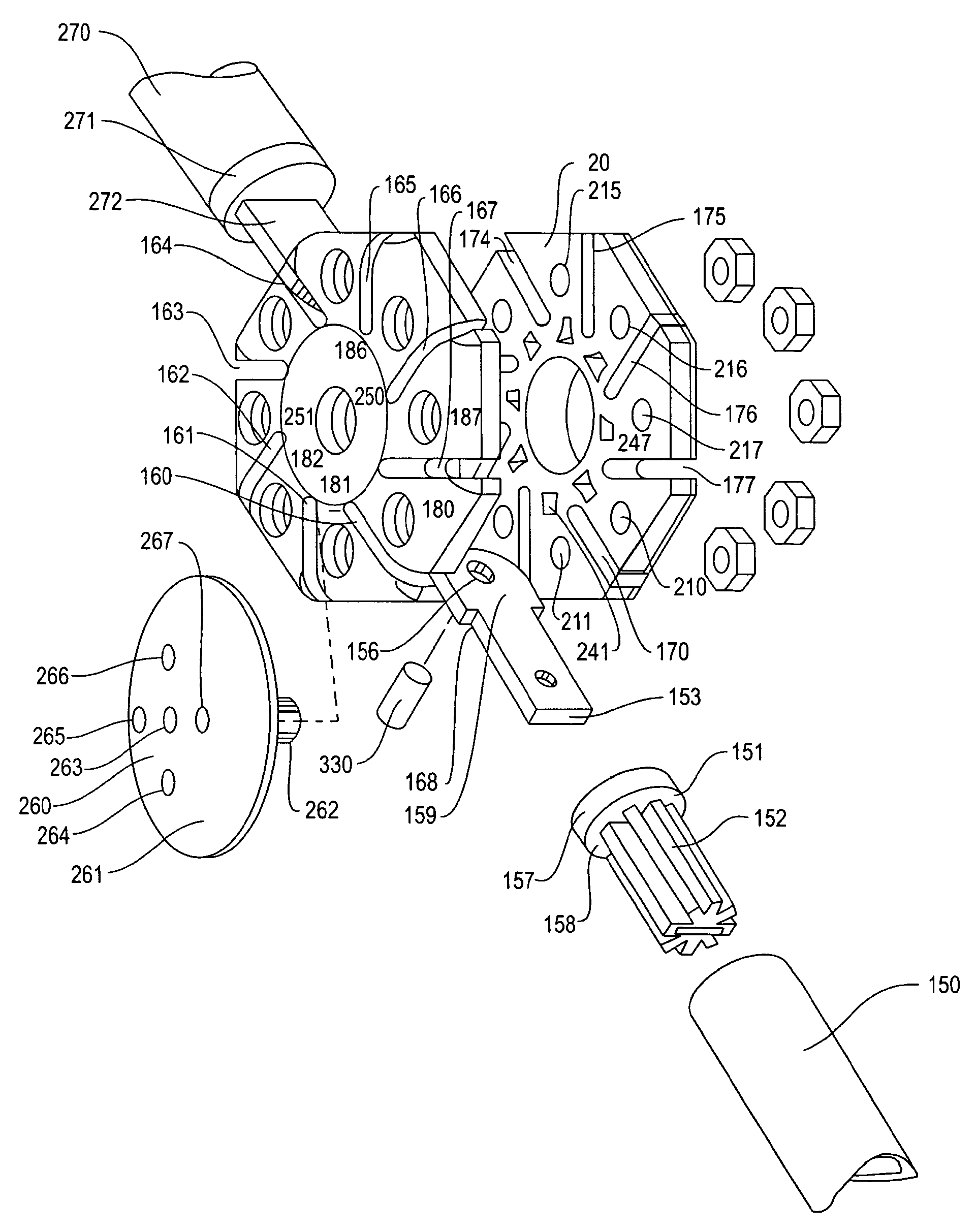
[0055]As noted above, the present invention relates to a deployable shelter and an articulating hub assembly which serves to connect tubular rods that comprise the basic construction elements for a prefabricated, self-supporting, deployable structure.

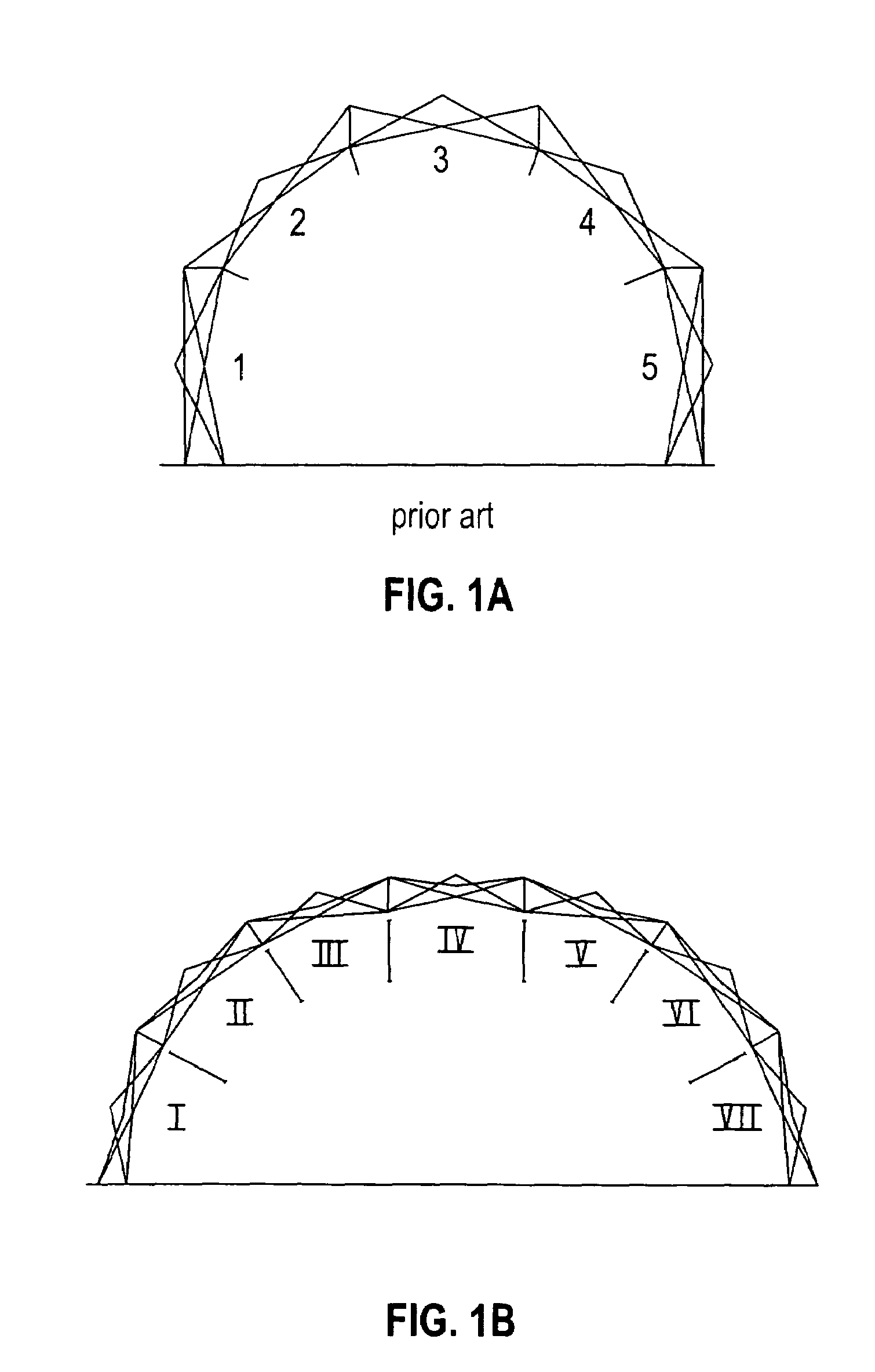
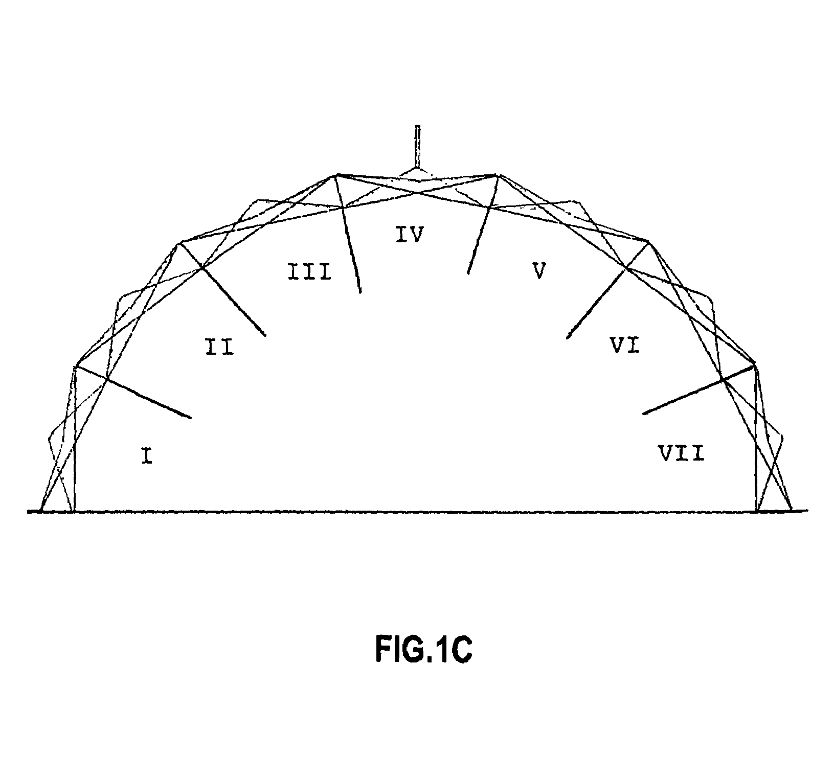
[0056]Tubular struts 150 and two hubs 8 and 9 of the present invention, with the tubular struts in their intermeshed orientations when the structure is in a folded state, are shown in FIG. 2. When viewing the hubs as depicted in FIG. 2, the “bottom” element, 10, of hub assembly 8, is shown connected to four tubular struts, and the “top” element, 11, of hub assembly 9 is shown also connected to four tubular struts. The tubular struts are connected to the hub by means of a plug 151 affixed within the interior of tubular strut 150. Plug 151 is connected to tang 154 which is held within the hub body 8. FIG. 2 shows only 7 struts for clarity.

[0057]FIG. 3 shows the “bottom”10 of hub assembly 8 of the present invention, with four tubular strut...


PUM


Abstract

A collapsible self-supporting structure used in combination with an improved articulating hub assembly. The articulating hub assembly is used as a connector among tubular rod elements which together provide a generally tubular frame matrix used to erect a collapsible self-supporting prefabricated deployable structure where a clear span interior without supporting columns is required.

Description

CROSS REFERENCE TO RELATED APPLICATION[0001]This application is related to my application Ser. No. 11 / 2228,651, filed Sep. 15, 2005.FIELD OF THE INVENTION[0002]The present invention relates to collapsible, self supporting structures and an improved articulating hub assembly used as a connector among tubular rod elements. The hub assembly and tubular rod elements provide a generally tubular frame matrix used to erect a collapsible self-supporting prefabricated deployable structures where a clear span interior without supporting columns is required.BACKGROUND OF THE INVENTION[0003]Portable deployable building assemblies must have a foldable capability so that they may be erected where desired and, when necessary, folded up to a compact form for storage and / or transportation. These portable building assemblies utilize struts, which are tubular rods, as the basic construction unit, that form the skeleton structure and thus the configuration of the portable building assembly. The tubular...

Claims


Application Information

Patent Timeline
Patent Type & Authority Patents(United States)
IPC IPC(8): E04H15/36E04B7/10
CPCE04H15/18E04H15/50Y10T403/343
Inventor PRUSMACK, A. JON
Owner HDT EXPEDITIONARY SYST INC
Why Eureka
Try Eureka