Apparatus and method for ligament fixation

a technology of apparatus and methods, applied in the field of surgical equipment and methods, can solve the problems of affecting the healing of the ligament to the bone, the risk of the ligament being slipped under load, and the necrosis of the tendon, so as to improve the resistance to the ligament being slipped under static and cyclic loading, the effect of augmenting the interference screw fixing the ligamen

Inactive Publication Date: 2009-02-03
CHAN KK
View PDF24 Cites 17 Cited by
  • Summary
  • Abstract
  • Description
  • Claims
  • Application Information

AI Technical Summary

Benefits of technology

[0014]Another object of the present invention is to provide an improved apparatus and method to resist slippage of the ligament in a bone tunnel under cyclic loading.
[0015]Yet another object of the present invention is to provide an improved apparatus and method for fixing a ligament in a bone tunnel without excessive sideways pressure on the ligament that may result in tissue necrosis.SUMMARY OF THE INVENTION
[0016]The present invention provides a jamming retainer to augment the interference screw fixation of a ligament in a bone tunnel, whereby resistance to slippage of the ligament under static and cyclic loading is improved. The invention also provides a jamming retainer for fixing a ligament in a bone tunnel without excessive sideways pressure on the ligament that may result in tissue necrosis. The jamming retainer includes a substantially rigid body with a bore or loop for attaching a ligament or tendon to the jamming retainer. The jamming retainer has a bore or ring for receiving a suture for towing the jamming retainer and ligament or tendon through a bone tunnel. Once the jamming retainer and ligament have been positioned within the bone tunnel, e.g., by towing, the ligament is fixed by insertion of an interference screw to compress the ligament sideways against the wall of the bone canal. However, as noted above, fixation achieved solely by engagement of the interference screw against the ligament is sometimes inadequate; however, with the present invention, this fixation is significantly improved through the use of the jamming retainer in one of two ways. In the first mode, sometimes hereinafter referred to as the “blocking mode”, the interference screw is advanced into the bone tunnel so as to be just touching, or just short of touching, the jamming retainer. Any subsequent proximal slippage of the ligament will draw the jamming retainer against the distal tip of the interference screw. Further slippage of the ligament is then prohibited by the jamming retainer abutting against the interference screw. In the second mode, sometimes hereinafter referred to as the “sideways compression mode”, the interference screw is advanced until the interference screw engages the jamming retainer and pushes the jamming retainer sideways, thus causing the jamming retainer to be partially embedded in the wall of the bone tunnel. Thus, the jamming retainer is fixed in position by its engagement with the interference screw and the wall of the bony tunnel.

Problems solved by technology

However, one disadvantage of direct fixation of the ligament in a bone tunnel with an interference screw is the risk of slippage of the ligament under load prior to the ligament healing to the bone.
Such slippage may occur during the rehabilitative period when the ligament is subjected to repetitive loading.
However, these large interference screws may cause necrosis of the tendon because of excessive compression of the ligament against the bony tunnel wall.

Method used


Image

  • Apparatus and method for ligament fixation
  • Apparatus and method for ligament fixation
  • Apparatus and method for ligament fixation

Examples


Embodiment Construction

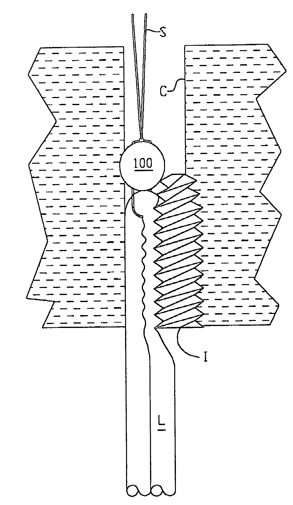
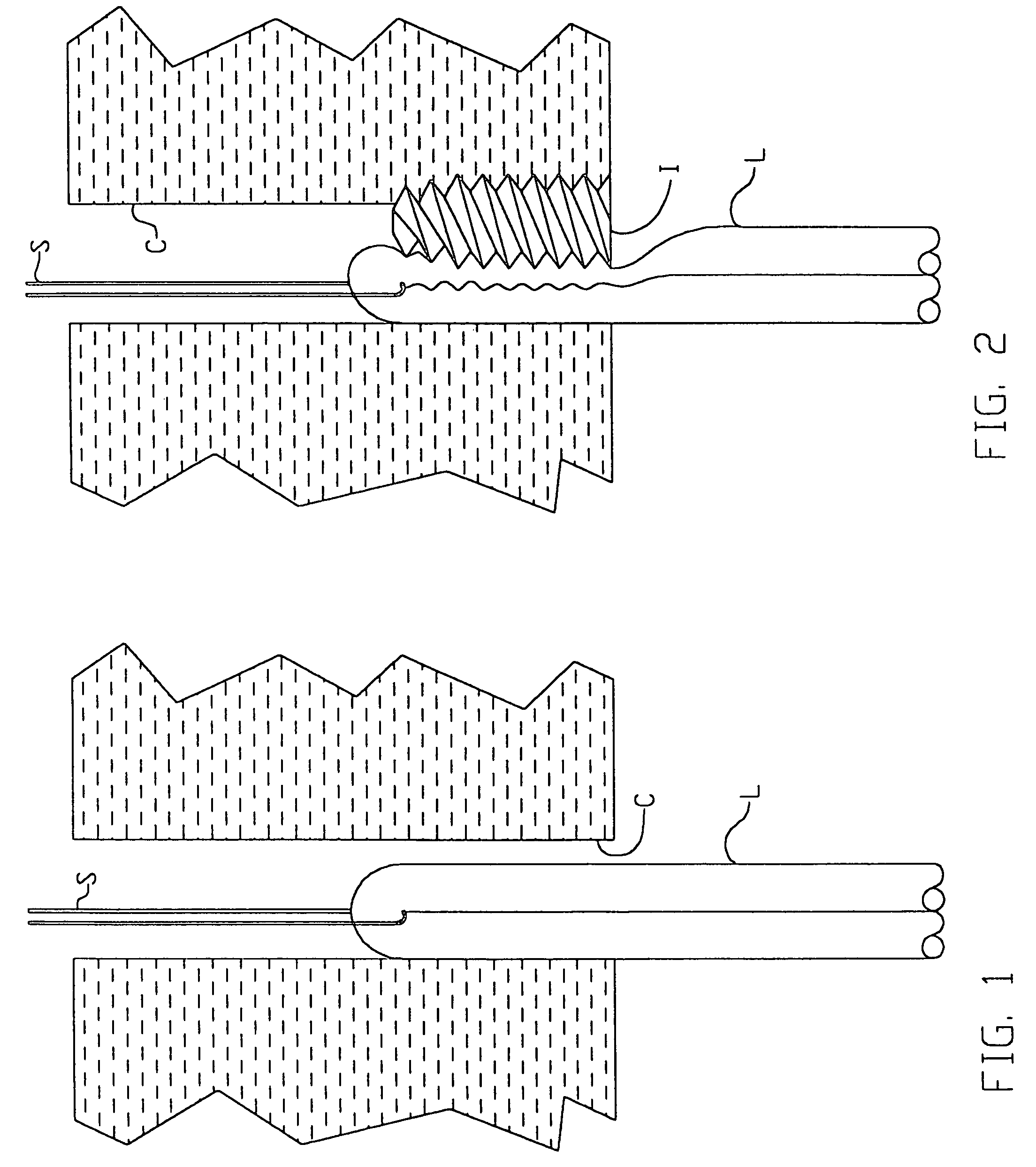
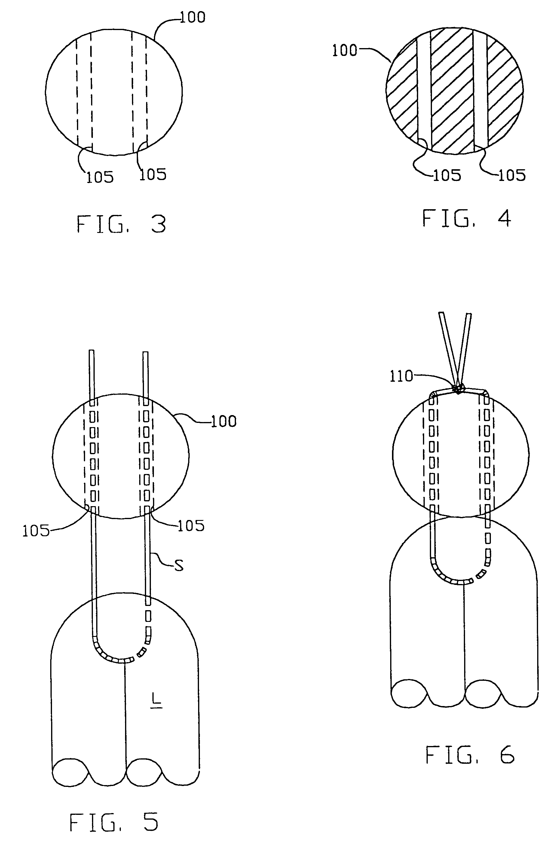
[0041]The present invention works in conjunction with a standard interference screw such as a Bioscrew (made by Linvatec) or an RCI screw (made by Smith and Nephew). The invention provides a jamming retainer which is attached to a ligament. The jamming retainer is positioned in a bone tunnel, and then, preferably, secured relative to the walls of the bone tunnel with an interference screw. More particularly, in one preferred embodiment, the interference screw urges the jamming retainer laterally against, and into, the wall of the bone tunnel. Interference between the jamming retainer and the walls of the bone tunnel fixes the ligament in the bone tunnel without ligament necrosis.

[0042]The interference screw also bears some of the load imparted on the jamming retainer by the ligament during normal use of the joint. Thus, even if the interference screw does not create a direct fixation between the jamming retainer and the wall of the bone tunnel, any slippage of the ligament will caus...


PUM


Abstract

A jamming retainer for fixing a ligament in a bone tunnel without excessive sideways pressure on the ligament that may result in tissue necrosis the jamming retainer including a substantially rigid body with a bore or loop for receiving a ligament or tendon and a bore or ring for receiving a suture for towing the jamming retainer and ligament or tendon through a bone tunnel. Once positioned, the jamming retainer is fixed in the bone tunnel with an interference screw.

Description

REFERENCE TO EARLIER APPLICATIONS[0001]This is a continuation of U.S. patent application Ser. No. 10 / 202,985, filed Jul. 24, 2002 by Kwan-Ho Chan for APPARATUS AND METHOD FOR LIGAMENT FIXATION which in turn is a division of U.S. patent application Ser. No. 09 / 315,918, filed May 20, 1999 now U.S. Pat. No. 6,562,043 by Kwan-Ho Chan for APPARATUS AND METHOD FOR LIGAMENT FIXATION which in turn claims benefit of (1) U.S. Provisional Patent Application Ser. No. 60 / 086,329, filed May 21, 1998 by Kwan-Ho Chan for APPARATUS AND METHOD FOR LIGAMENT FIXATION and (2) U.S. Provisional Patent Application Ser. No. 60 / 125,745, filed Mar. 23, 1999 by Kwan-Ho Chan for APPARATUS AND METHOD FOR LIGAMENT FIXATION which patent applications are hereby incorporated herein by reference.FIELD OF THE INVENTION[0002]The present invention relates to surgical apparatus and methods in general, and more particularly to apparatus and methods for fixing a ligament in a bone tunnel.BACKGROUND OF THE INVENTION[0003]Th...

Claims


Application Information

Patent Timeline
Patent Type & Authority Patents(United States)
IPC IPC(8): A61F2/08
CPCA61F2/0811A61B2017/0403A61B2017/0414A61B2017/044A61B2017/0448A61B2017/0451A61F2/0805A61F2002/0829A61F2002/0835A61F2002/0852A61F2002/0858A61F2002/0864A61F2002/087A61F2002/0882
Inventor CHAN, KWAN-HO
Owner CHAN KK
Why Eureka
Try Eureka