
Notification/alert motion for electronic equipment and or devices

a technology of applied in the direction of instruments, horology, electric winding, etc., can solve the problems of limited current options available for notification or alerting, limited current options available, and limited options for electronic equipment and or devices

Inactive Publication Date: 2009-02-17
OSBORNE MORGAN KENNEDY
View PDF2 Cites 5 Cited by
  • Summary
  • Abstract
  • Description
  • Claims
  • Application Information

AI Technical Summary

Problems solved by technology

Electronic equipment and or devices today have limited options in notifying or alerting attention to the individual owner / consumer and or equipment and or device.
Such current options available today of notification or alerting are limited to: noise, vibration and light.
The current options available are limited and might / could / will / should / need / would not be the desired type of notification or alerting of certain individuals / consumers.
This presents a major problem.

Method used


Image

  • Notification/alert motion for electronic equipment and or devices
  • Notification/alert motion for electronic equipment and or devices
  • Notification/alert motion for electronic equipment and or devices

Examples


Embodiment Construction

FIGS. 1A and 1B—Preferred Embodiment

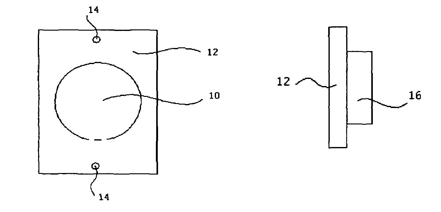
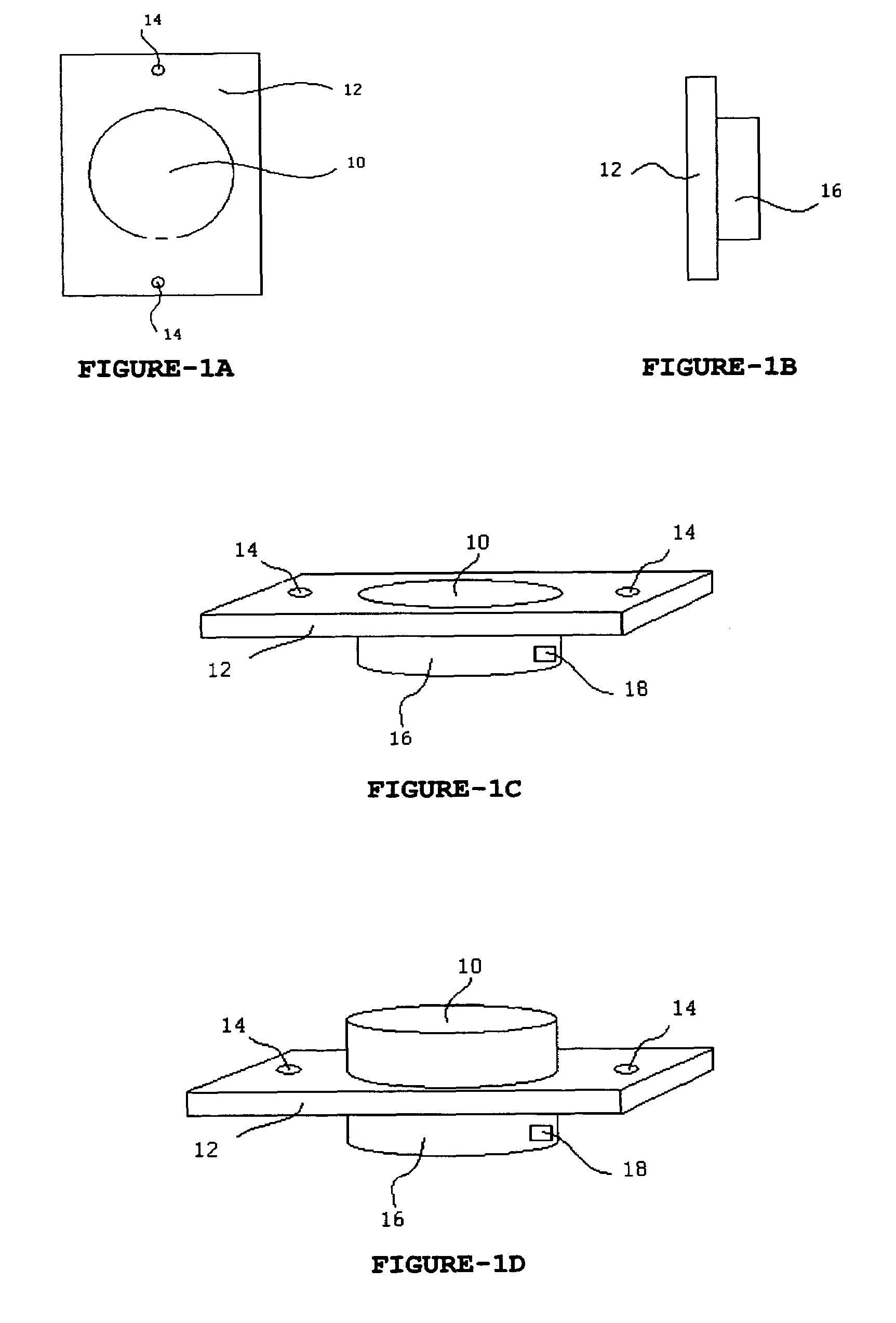
[0047]A preferred embodiment of the invention is illustrated in FIGS. 1A to 1D&3A. The invention has a thin housing (12) made of plastic necessary to hold / store / house the power spring / motor (10) and attach itself to electrical equipment / object and or devices using the screw holes (14) to be secured by screws.

[0048]When properly secured to the intended object, the invention is flush with it's surroundings. When set on the ground (with power spring / motor stored) it will lay flat.

[0049]The top of the power spring / motor (10) is to be covered with a rubbery material as to provide grip when invention is in it's active mode of spinning.

[0050]The housing storage for power spring / motor (16) has an entrance / location for the electrical connect / trigger (18) as to where the invention is electrically connected to the electrical equipment and or device / object.

OPERATION

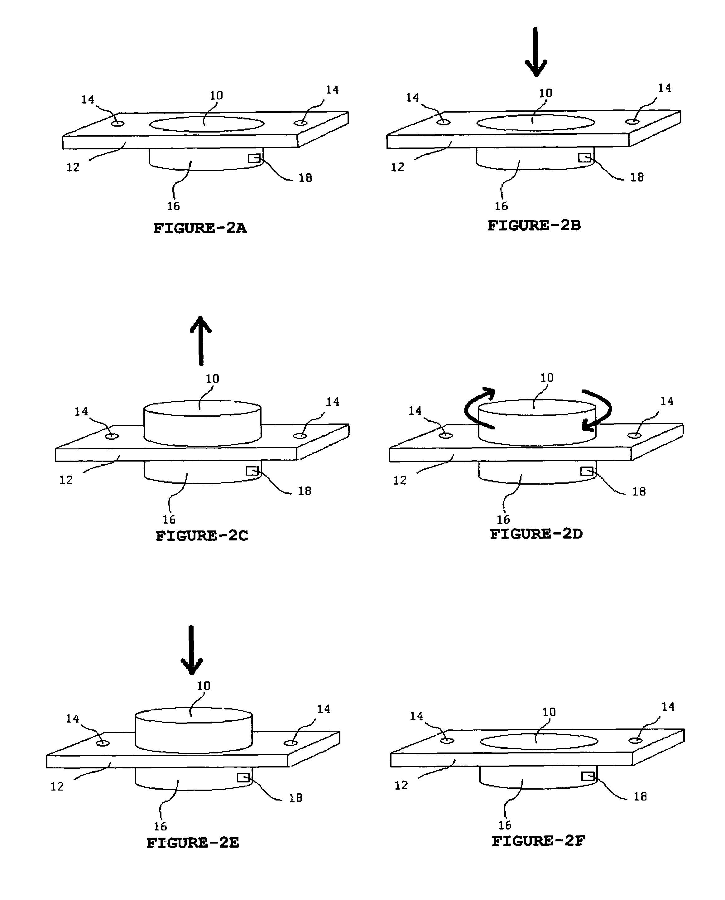
FIGS. 2A, 2B, 2C, 2D, 2E, 2f, 2G, 2H, 2I, 2J, 3A &4A

[0051]After being properly attached to the ...


PUM


Abstract

A motion producing motion-based notification / alert device to be used in and for attachment to mobile electronic equipment or devices, where the motion producing motion-based notification / alert device, upon receipt of an electronic signal from the mobile electronic equipment or device, reacts to set the mobile electronic equipment or device into various elevations and motions. The motion producing motion-based notification / alert device is designed to receive electronic signals from the mobile electronic equipment or device, whereby producing various motions resulting in the owner or user of the mobile electronic equipment or device being notified / alerted that the mobile electronic equipment or device has received an incoming signal or a desired event of the mobile electronic equipment or device has taken place. The motion producing motion-based notification / alert device includes a housing containing a power spring / electric motor which can be used in or attached to the mobile electronic equipment or device.

Description

CROSS-REFERENCE TO RELATED APPLICATIONS[0001]NoneFEDERALLY SPONSORED RESEARCH[0002]NoneSEQUENCE LISTING OR PROGRAM[0003]NoneBACKGROUND OF THE INVENTION[0004]1. Field of Invention[0005]This invention relates to all electronic equipment and or devices, specifically related to the alerting or notification of the / a desired event by delivery of an electronic charge to the invention thus setting the attached electronic equipment and or device into motion.[0006]Such electronic equipment and or devices intended are, but not limited to, such: Cellular Phones, Cell-Phones, Cell Phone, Mobile Phones, Mobile Telephones, Telephones, Personal Digital Assistant, PDA's, Handheld PC, Handheld Devices, Personal Computers, Handheld Computers, Radio Telephone, Transmitters, Electronic Receivers, Pagers, Handheld Devices, Music Storage Devices, Music Players, Remote Controls, Calculators, etc.[0007]2. Prior Art[0008]Electronic equipment and or devices today have limited options in notifying or alerting ...

Claims


Application Information

Patent Timeline
Patent Type & Authority Patents(United States)
IPC IPC(8): G08B7/00
CPCG08B7/02H04M1/0202H04M19/04
Inventor OSBORNE, MORGAN KENNEDY
Owner OSBORNE MORGAN KENNEDY
Learn More