Surgical stapling device

a surgical and stapling technology, applied in the direction of surgical staples, surgical forceps, applications, etc., can solve the problems of difficulty for surgeons to manipulate the tool assembly of instruments to access and/or clamp tissu

Active Publication Date: 2009-02-24
TYCO HEALTHCARE GRP LP
View PDF436 Cites 1850 Cited by
  • Summary
  • Abstract
  • Description
  • Claims
  • Application Information

AI Technical Summary

Benefits of technology

[0017]In a final embodiment, an outer tube may deform a leaf spring in transitioning from a retracted position to an advanced position.

Problems solved by technology

Due to the limited degree of motion of an instrument when it is positioned through the skin, it may be quite difficult for a surgeon to manipulate the tool assembly of the instrument to access and / or clamp tissue.

Method used


Image

  • Surgical stapling device
  • Surgical stapling device
  • Surgical stapling device

Examples


Embodiment Construction

[0107]Preferred embodiments of the presently disclosed stapling device will now be described in detail with reference to the drawings in which like reference numerals designate identical or corresponding element in each of the several views.

[0108]U.S. provisional application Ser. No. 60 / 416,088 filed Oct. 4, 2002, now expired, and U.S. provisional application Ser. No. 60 / 416,372 filed Oct. 4, 2002, now expired are incorporated herein by reference in their entirety.

[0109]Throughout this description, the term “proximal” will refer to the portion of the device closest to the operator and the term “distal” will refer to the portion of the device furthest from the operator.

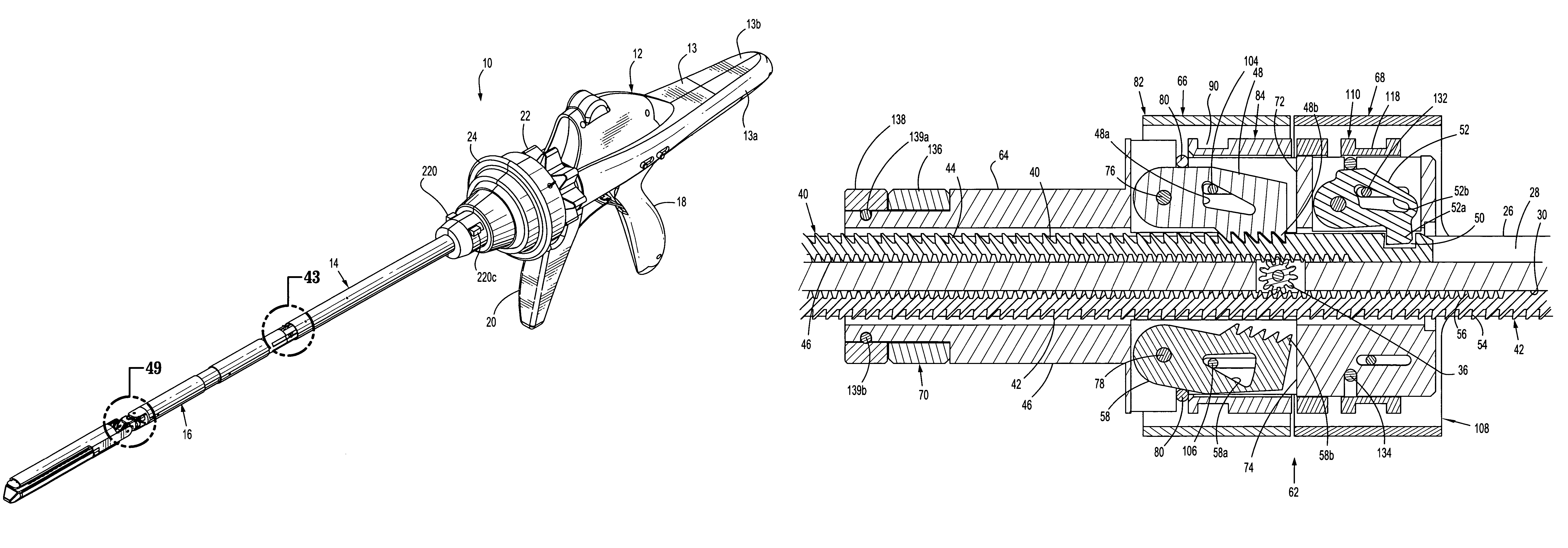
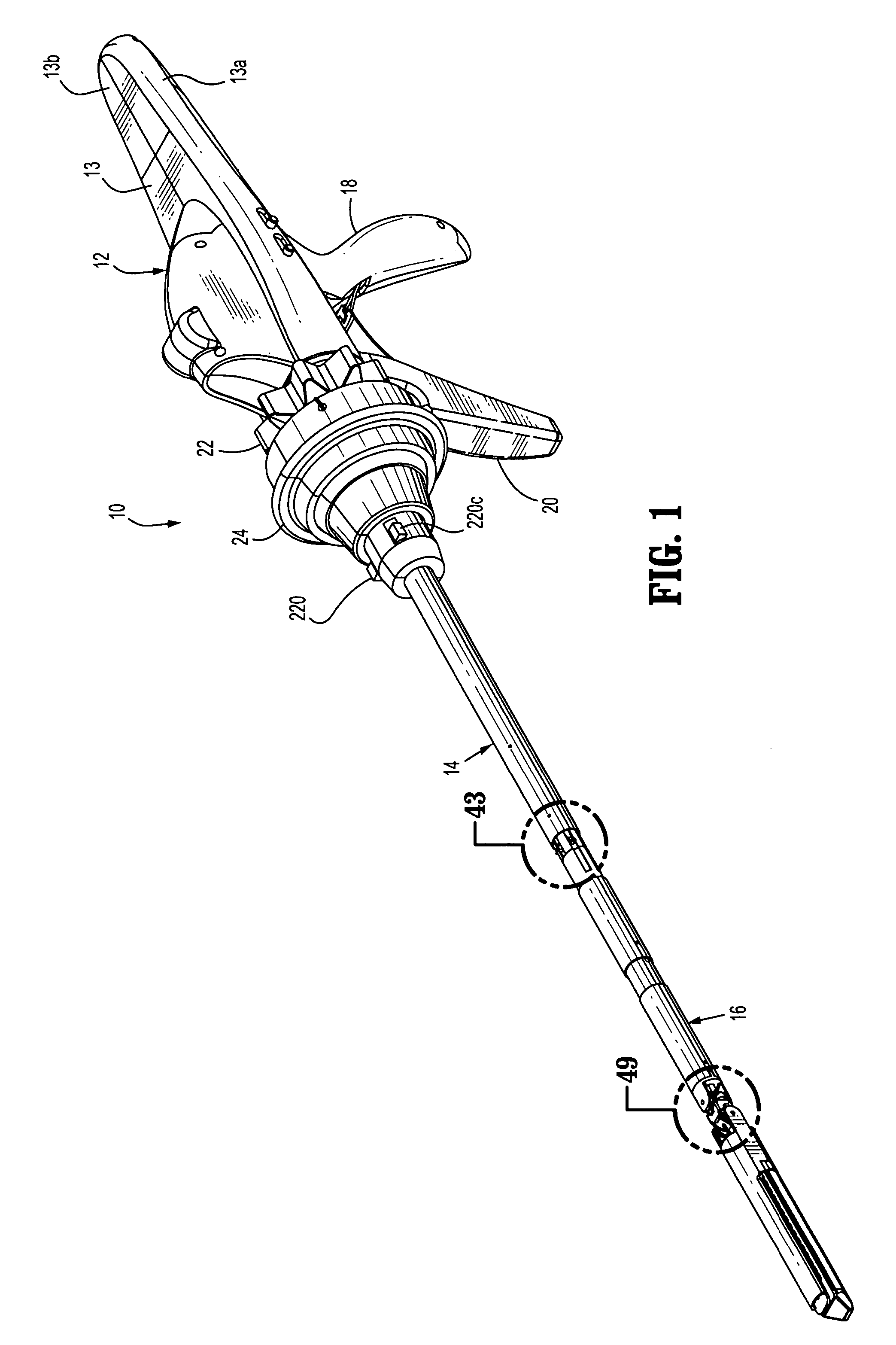
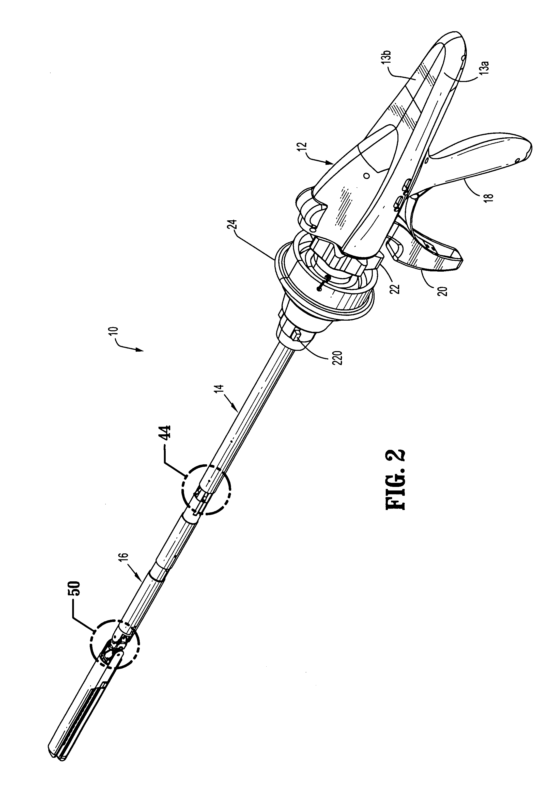
[0110]FIGS. 1-8 illustrate one embodiment of the presently disclosed surgical stapling device shown generally as 10. Briefly, surgical stapling device 10 includes a proximal handle portion 12, an elongated central body portion 14 and a distal disposable loading unit (“DLU”) 16. Preferably, the DLU is a single use loadi...


PUM

PropertyMeasurementUnit
sizeaaaaaaaaaa
sizeaaaaaaaaaa
sizeaaaaaaaaaa

Abstract

A surgical device is disclosed which includes a handle portion, a central body portion and a SULU. The SULU includes a proximal body portion, an intermediate pivot member and a tool assembly. The intermediate pivot member is pivotally secured to the proximal body portion about a first pivot axis and the tool assembly is pivotally secured to the intermediate pivot member about a second pivot axis which is orthogonal to the first pivot axis. The SULU includes a plurality of articulation links which are operably connected to the tool assembly by non-rigid links. The articulation links are adapted to releasably engage articulation links positioned in the central body portion. The body portion articulation links are connected to an articulation actuator which is supported for omni-directional movement to effect articulation of the tool assembly about the first and second axes. The handle portion includes a spindle and barrel assembly drive mechanism for advancing and retracting a drive member positioned in the tool assembly. In one embodiment, the tool assembly includes a cartridge assembly having a plurality of staples and an anvil assembly.

Description

CROSS REFERENCE TO RELATED APPLICATIONS[0001]This application is a continuation application of copending U.S. application Ser. No. 11 / 894,195, filed Aug. 20, 2007, which is a continuation application of U.S. application Ser. No. 11 / 652,756, filed Jan. 12, 2007, now U.S. Pat. No. 7,424,965 which is a continuation application of copending U.S. application Ser. No. 11 / 543,640 filed Oct. 3, 2006, which is a divisional application of U.S. application Ser. No. 10 / 871,342 filed Jun. 17, 2004, now U.S. Pat. No. 7,159,750, which claims priority to U.S. Provisional Patent Application Ser. No. 60 / 479,379, filed Jun. 17, 2003, now expired. Each of these applications are incorporated by reference herein in their entirety.BACKGROUND[0002]1. Technical Field[0003]The present disclosure relates to a surgical stapling device and, more particularly, to an endoscopic surgical stapling device having a tool assembly which is articulatable about first and second perpendicular axes.[0004]2. Background of R...

Claims


Application Information

Patent Timeline
Patent Type & Authority Patents(United States)
IPC IPC(8): A61B17/04
CPCA61B17/07207A61B2017/07278A61B2017/2927A61B2017/320052A61B2019/2242A61B34/71
Inventor RACENET, DAVID C.STEARNS, RALPHBEARDSLEY, JOHN W.ROY, PHILIPOLSON, LEE ANN
Owner TYCO HEALTHCARE GRP LP
Why Eureka
Try Eureka