Planter bracket assembly for supporting appurtenances in substantial alignment with the seed tube

a planter bracket and appurtenance technology, which is applied in the direction of potato planters, furrow making/covering, agricultural tools and machines, etc., can solve the problems of affecting the flow of liquid applicator tubes, and affecting the stability of the liquid applicator tubes

Active Publication Date: 2009-03-03
PRECISION PLANTING LLC
View PDF30 Cites 55 Cited by
  • Summary
  • Abstract
  • Description
  • Claims
  • Application Information

AI Technical Summary

Benefits of technology

[0011]In another embodiment, the bracket assembly includes a shaft mount, a shank mount and a housing adapted to operably support one or more seed planting appurtenances in substantial alignment with the seed tube. In a preferred embodiment, the shank mount includes both a forward shank-engaging mount and a rearward shank-engaging mount thereby providing a more universal bracket adaptable for use with most planters.

Problems solved by technology

Attaching resilient tools directly to the seed tube, is often time consuming and difficult due to the confined space.
Furthermore, attaching resilient tools directly to the seed tube can place undue stress on the seed tube if the resilient tool makes soil contact during planting operations.
It has been found that sharp bends in the applicator tubes may cause restriction in the flow of the liquid fertilizers, and, over time, the liquid fertilizers can congeal at these sharp bends, further restricting the flow through the liquid applicator tubes.
Furthermore, at least with respect to the bracket assembly of FIG. 2, it has been found that the mounting ears that attach the bracket assembly to the axle of the furrow opening discs, which are made of thermoplastic material, may eventually wear, break or tear after extended periods of use, requiring replacement of the bracket assembly.

Method used


Image

  • Planter bracket assembly for supporting appurtenances in substantial alignment with the seed tube
  • Planter bracket assembly for supporting appurtenances in substantial alignment with the seed tube
  • Planter bracket assembly for supporting appurtenances in substantial alignment with the seed tube

Examples


first embodiment

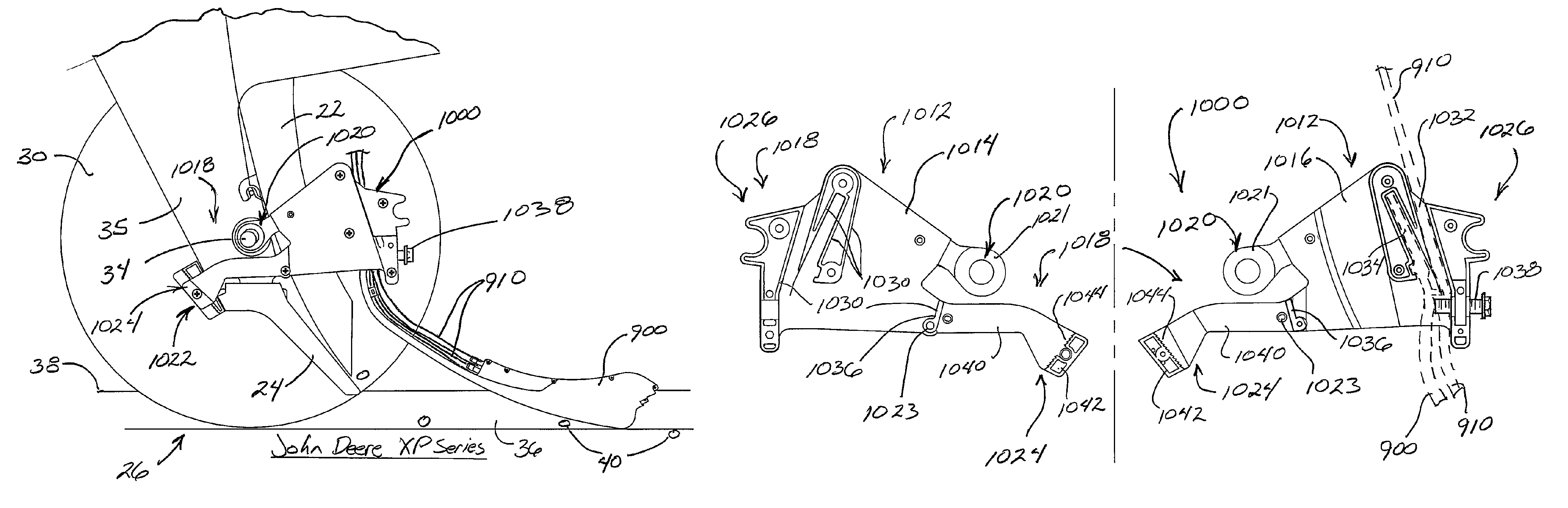
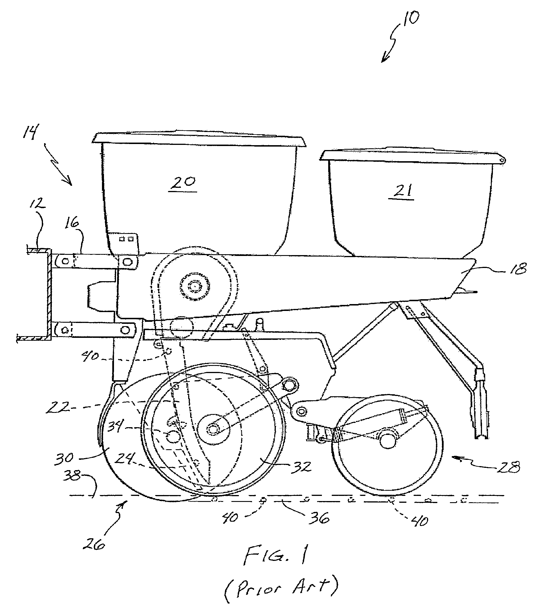
[0046]FIGS. 6-14 illustrate various embodiments of improved bracket assemblies comprising the present invention. Referring, first to FIG. 6, an improved bracket assembly 300 is shown. As with the existing bracket assembly 100, this first improved bracket assembly 300 comprises a housing 312 having opposing, preferably substantially mirror-image, first and second sides 314, 316. The housing 312 preferably includes mounting structure 318 comprising upper and lower ears 320, 322. However, rather than the ears 320, 322 formed from thermoplastic material as in the existing bracket assembly 100, the upper ears 320 comprise metal ear tabs preferably integrally attached with the housing 312 by inserting molding the metal ear tabs 320 during the injection molding process when forming the housing 312. Alternatively, rather than insert molding, the metal ear tabs 320 may be integrally attached to the housing 312 by a rivet connection, bolted connection, adhesives or welding by any know means, ...

embodiment 500

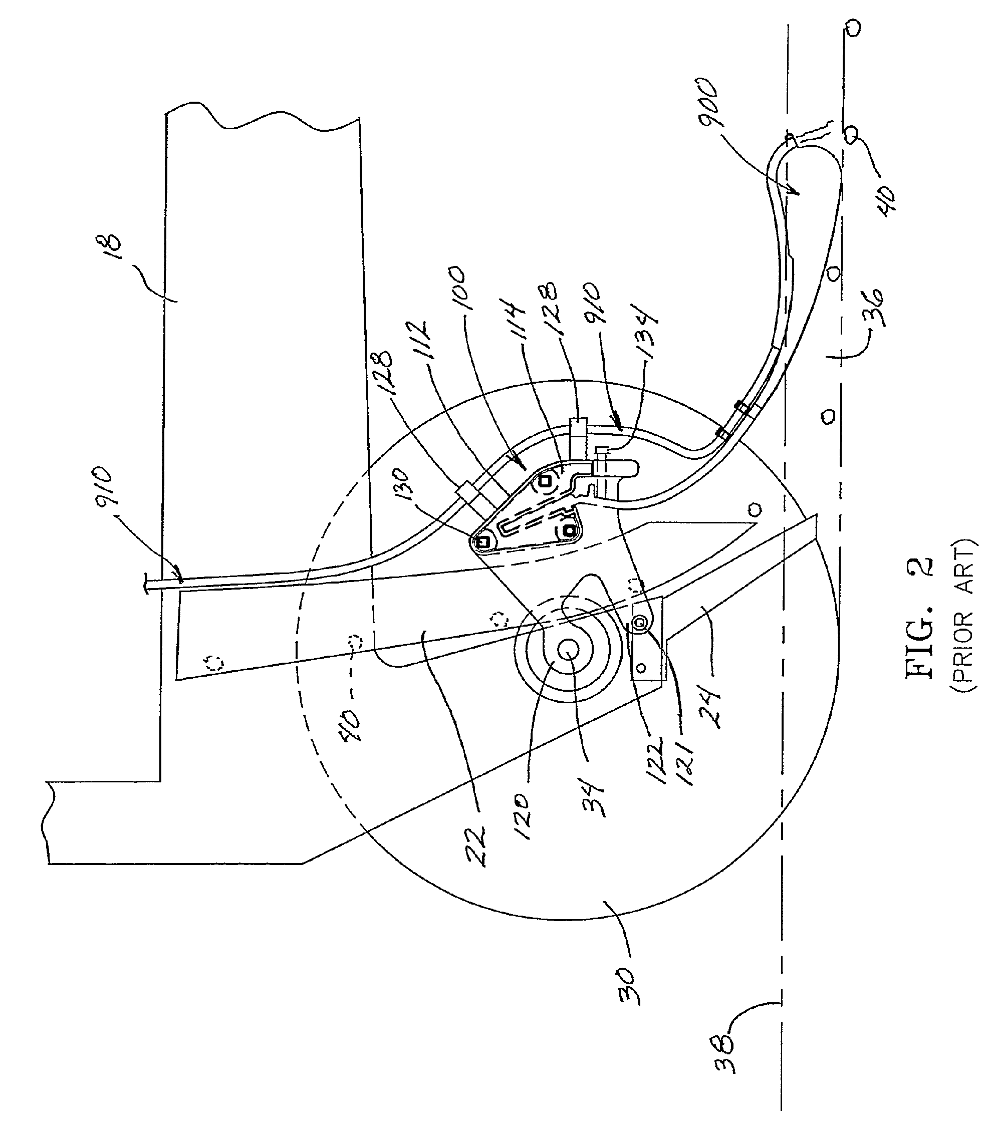
[0055]As previously identified, the third improved bracket assembly embodiment 500 includes a passageway 528 defined by the walls 524. The passageway 528 extends through at least a portion of the housing 512 through which a liquid conduit 910 is receivable. Accordingly, if in-furrow liquid application is desired, one end of the liquid conduit 910 is inserted through the passageway 528 within the housing 512. Depending on the type of resilient tool 900 installed in the cavity 526, the liquid conduit 910 may extend along the back of the resilient tool 900, terminating at the rearward end of the resilient tool 900 as shown in FIG. 11. The other end of the liquid conduit 910 is fluidly connected to a liquid supply reservoir (not shown) located on the planter or prime mover. In operation, liquid is pumped from the liquid supply reservoir through the liquid conduit 910 for depositing in the furrow, preferably behind the resilient tool 900.

[0056]It should be understood that although the pr...


PUM


Abstract

A bracket assembly for supporting seed planting appurtenances in substantial alignment with respect to a seed tube of an agricultural planter. The bracket assembly includes a shaft mount and a shank mount.

Description

CROSS REFERENCE TO RELATED APPLICATIONS[0001]This application is a continuation-in-part of U.S. patent application Ser. No. 10 / 666,108 filed Sep. 18, 2003, now U.S. Pat. No. 6,918,342.BACKGROUND OF THE INVENTION[0002]In recent years, farmers have begun to recognize and appreciate the importance of ensuring accurate and consistent spacing of seeds in the furrow to improve crop yields. To ensure more accurate in-furrow seed placement, farmers have begun attaching various types of tools or appurtenances, such as seed deflectors and seed firmers, to the seed tube of the planter to minimize in-furrow seed bounce or roll.[0003]Examples of various types of seed deflectors adapted to be mounted directly to the seed tube are disclosed in U.S. Pat. No. 2,533,374 issued to Hyland; U.S. Pat. No. 5,092,255 issued to Long et al.; and U.S. Pat. No. 6,283,050 issued to Schaffert. Examples of various types of seed firmers adapted to be secured directly to the seed tube are disclosed in U.S. Pat. Nos...

Claims


Application Information

Patent Timeline
Patent Type & Authority Patents(United States)
IPC IPC(8): A01C5/00A01C13/00A01C7/00A01C9/00A01C23/00A01C5/06A01C7/20
CPCA01C5/068A01C7/20A01C7/06
Inventor SAUDER, DEREK A.PLATTNER, CHAD
Owner PRECISION PLANTING LLC
Why Eureka
Try Eureka