Battery charger with booster pack

a battery charger and booster pack technology, applied in the direction of electric/fluid circuit, transportation and packaging, dc network circuit arrangement, etc., can solve the problems of battery not being able to provide the necessary cranking power, battery depletion or “dead” battery not being able to start the vehicle, and usually not being able to be recharged easily

Inactive Publication Date: 2009-03-10
MIDTRONICS
View PDF403 Cites 82 Cited by
  • Summary
  • Abstract
  • Description
  • Claims
  • Application Information

AI Technical Summary

Problems solved by technology

Circumstances may occur that cause the vehicle battery charge to deplete so that the battery is incapable of starting the vehicle.
Such conditions normally arise due to the fact that the operator of the vehicle has inadvertently left the lights, radio, or other energy consuming device or accessory running in the vehicle after the vehicle ignition has been turned off.
Such a depleted or “dead” battery is incapable of providing the necessary cranking power to start the vehicle.
The disadvantage of a battery charger is that it typically needs to be connected to an alternating current (AC) supply which may not be accessible where the vehicle battery dies.
A disadvantage of a jump-start booster battery is that it usually cannot be recharged easily and may be in a depleted condition when it is required to charge a dead battery.

Method used


Image

  • Battery charger with booster pack
  • Battery charger with booster pack
  • Battery charger with booster pack

Examples


Embodiment Construction

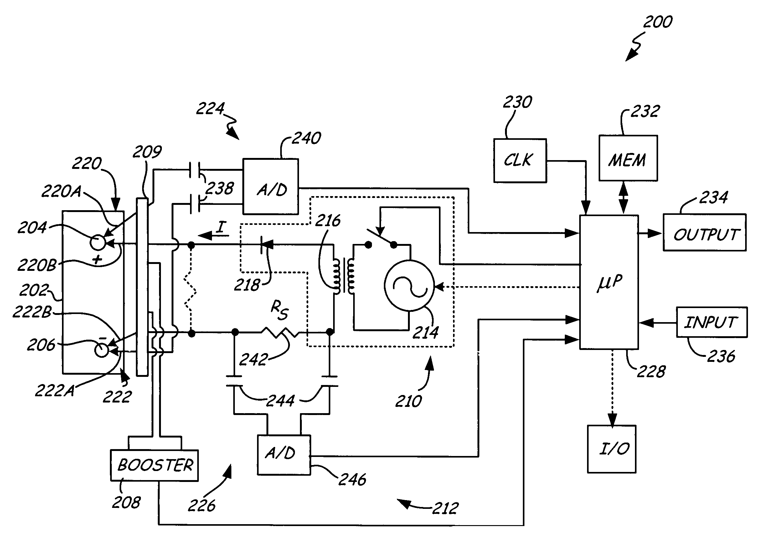
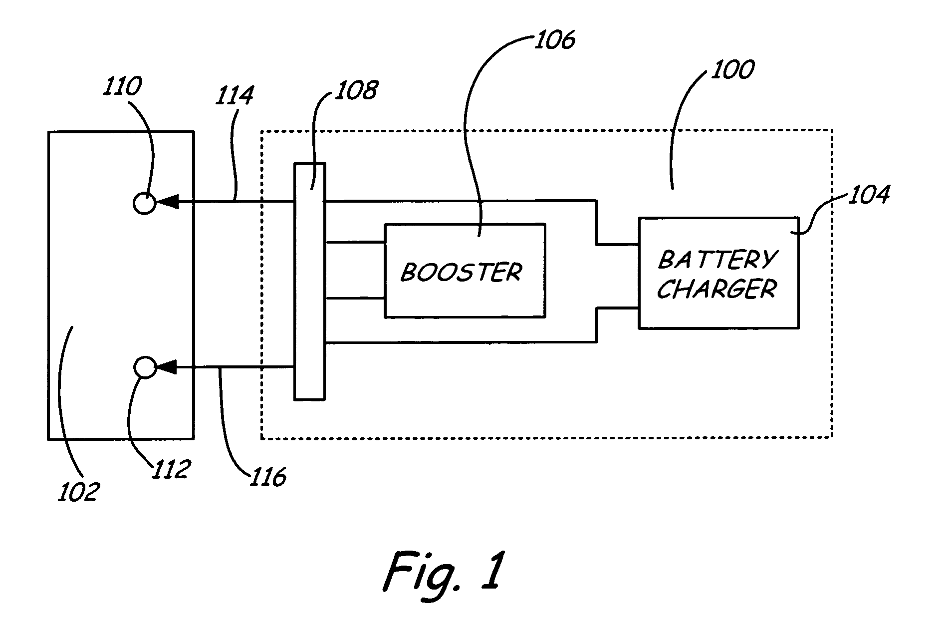
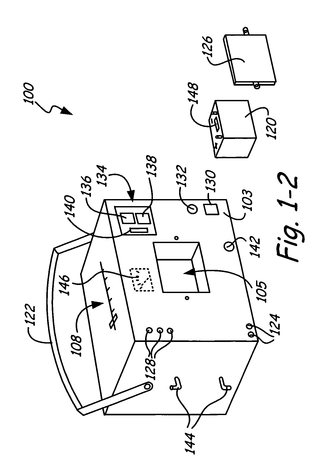
[0013]FIG. 1-1 is a simplified block diagram of a battery charger with an integrated jump-start booster pack in accordance with an embodiment of the present invention. The same reference numerals are used in the various figures to represent the same or similar elements. System 100 is shown coupled to a vehicle battery 102. System 100 includes battery charging circuitry 104, jump-start booster pack 106 and mode selection switch 108. System 100 couples to battery contacts 110 and 112 through electrical connections 114 and 116 respectively. Details and components of a battery charging circuit 104 are provided further below in connection with FIG. 2-1. Jump-start booster pack 106, which is described further below in connection with FIG. 2-2, typically includes an internal booster battery of the same terminal voltage as vehicle battery 102 but is of much smaller capacity. Mode selection switch 108 can be set in different positions, with each position corresponding to a different mode in ...


PUM


Abstract

An apparatus and method for supplying energy to a vehicle battery is provided. The apparatus includes a positive connector that couples to a positive terminal of the vehicle battery and a negative connector that couples to a negative terminal of the vehicle battery. A battery charger applies a charge signal to the vehicle battery through the positive and negative connectors to thereby charge the vehicle battery. A jump-start booster pack, coupled to the battery charger, can optionally provide starting energy to the vehicle battery through the positive and negative connectors. The booster pack can be charged by the charge signal. In one aspect, the battery charger is a switch-mode charger.

Description

CROSS REFERENCE TO RELATED APPLICATION[0001]The present application is a Continuation-In-Part of U.S. patent application Ser. No. 10 / 177,635, filed Jun. 21, 2002 which is based on and claims the benefit of U.S. Provisional Application Ser. No. 60 / 300,386, filed Jun. 22, 2001.BACKGROUND OF THE INVENTION[0002]The present invention relates to rechargeable storage batteries. More specifically, the present invention relates to a battery charger / tester with an integrated jump-start booster pack for use with such storage batteries.[0003]Chemical batteries which create electricity from chemical reactions have been known for many years. Such batteries are becoming increasingly important and have found uses throughout industry. These uses include automobiles, UPS systems, etc.[0004]One advantage of chemical batteries, such as lead acid storage batteries, is that they can be charged and the chemical process reversed by forcing electricity through the battery. Charging systems are widely known ...

Claims


Application Information

Patent Timeline
Patent Type & Authority Patents(United States)
IPC IPC(8): H02J7/00B60R16/02B60R16/03
CPCH02J7/0054B60R16/03H02J2001/006H02J1/122H02J7/342H02J2310/46
Inventor BERTNESS, KEVIN I.VONDERHAAR, J. DAVID
Owner MIDTRONICS
Why Eureka
Try Eureka