Current-limiting battery usage within a corded electronic device

Active Publication Date: 2014-02-13
HONEYWELL SCANNING & MOBILITY
View PDF7 Cites 641 Cited by
  • Summary
  • Abstract
  • Description
  • Claims
  • Application Information

AI Technical Summary

Problems solved by technology

Moreover, the device may draw additional power from the battery as necessary to perform one or more operations that may otherwise exceed the limitations of the corded electrical interface.

Method used


Image

  • Current-limiting battery usage within a corded electronic device
  • Current-limiting battery usage within a corded electronic device
  • Current-limiting battery usage within a corded electronic device

Examples


Embodiment Construction

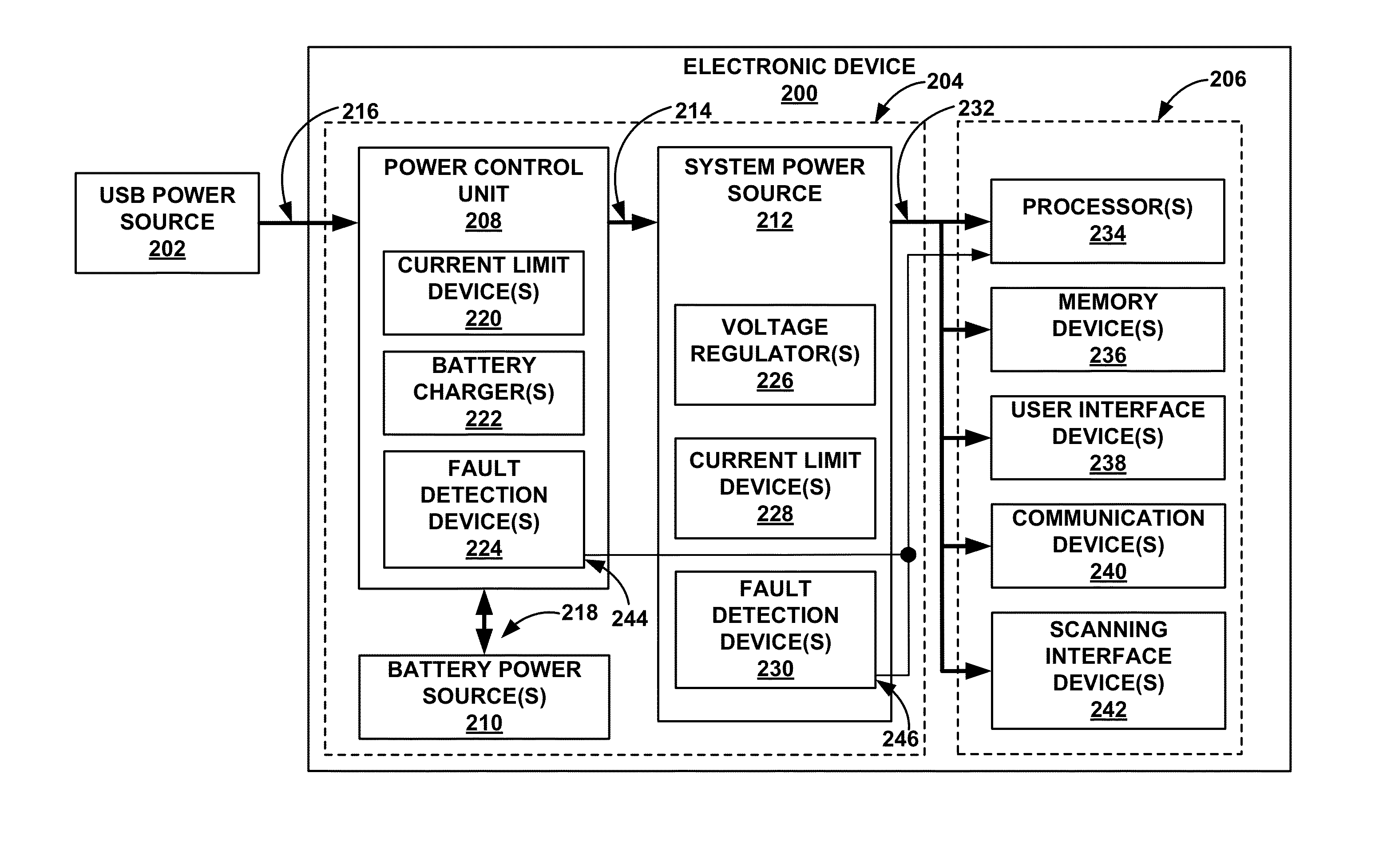
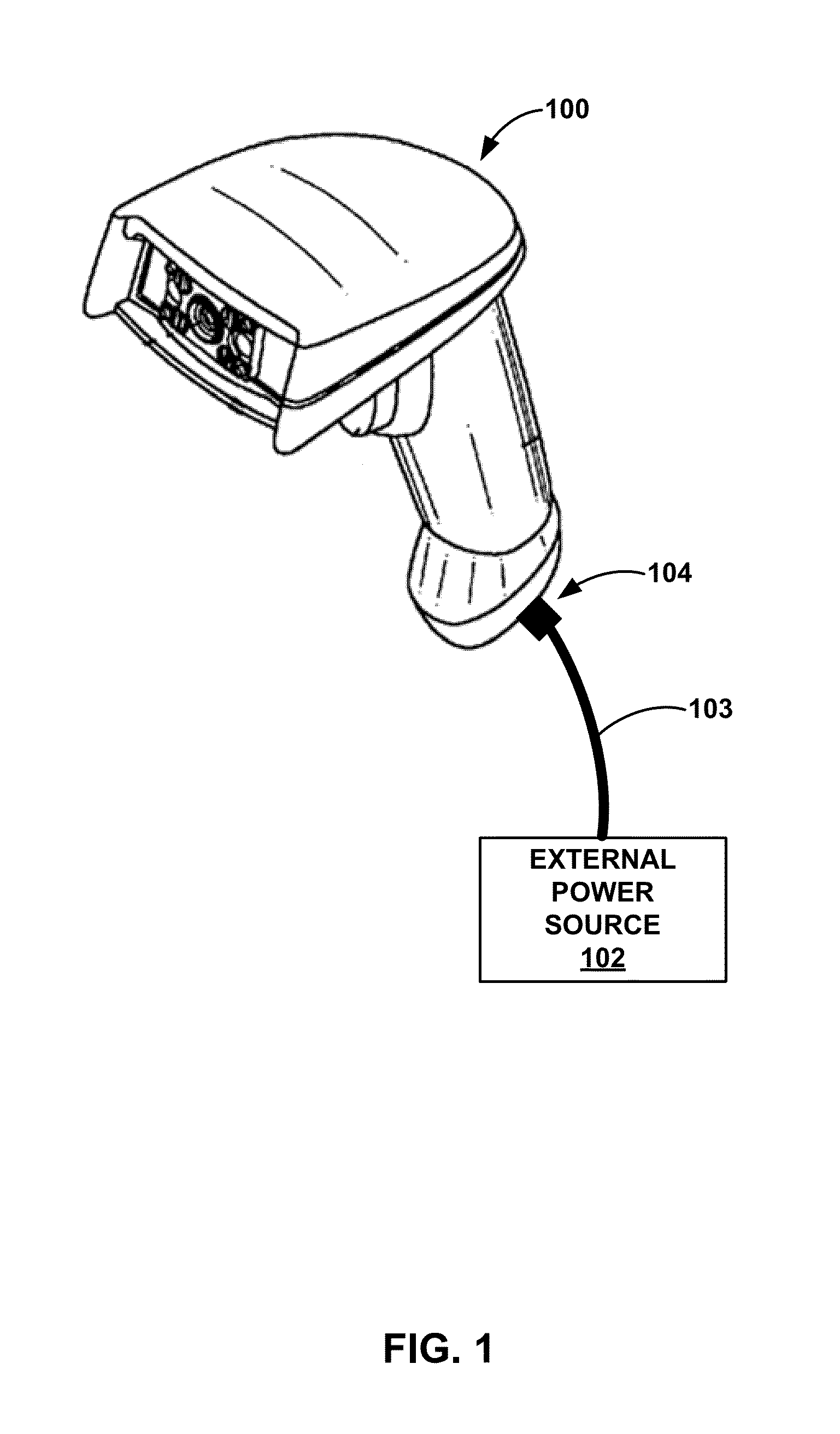
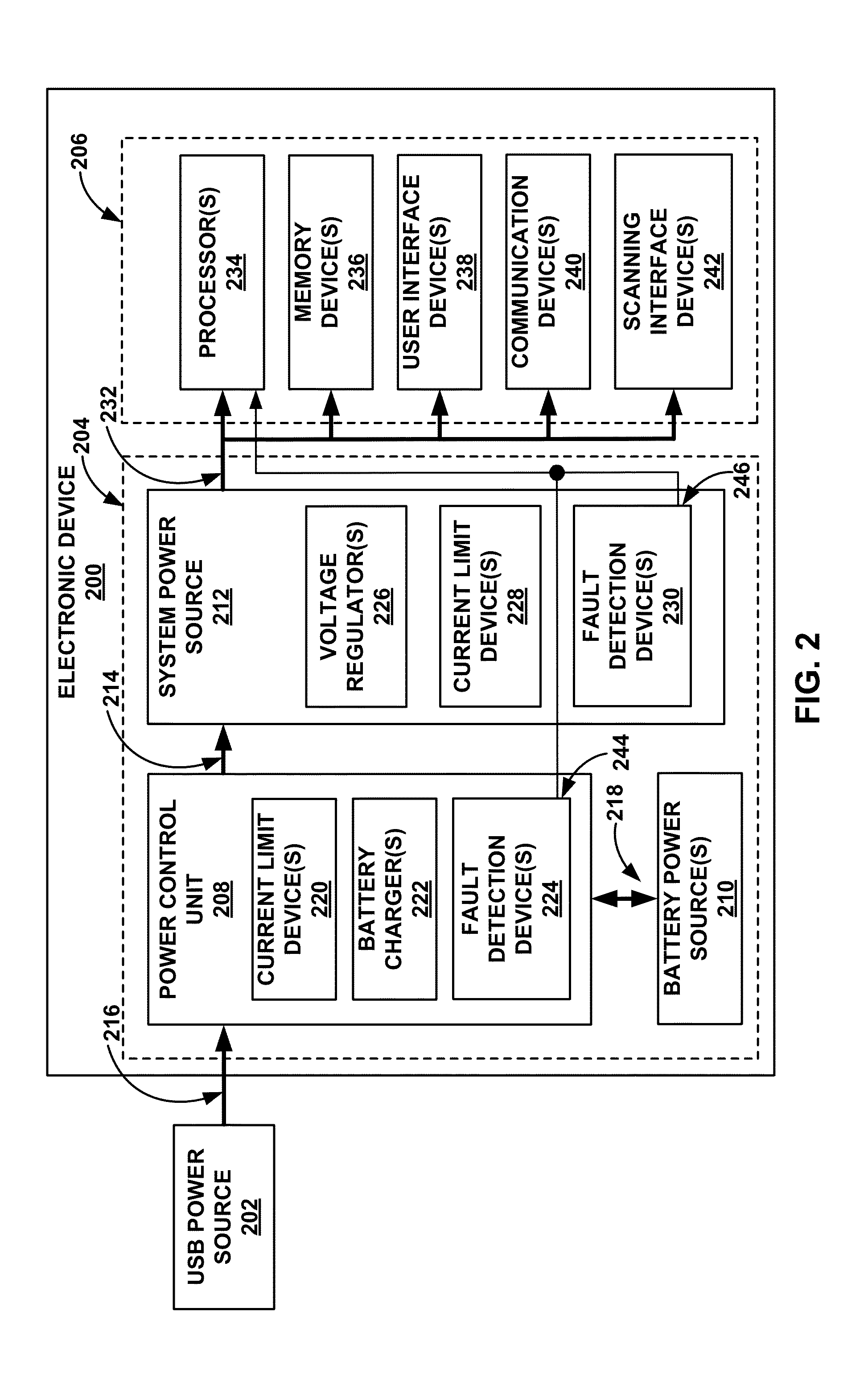
[0015]FIG. 1 is a diagram that illustrates one example of a corded electronic device, consistent with the techniques of this disclosure. In the example shown in FIG. 1, corded electronic device 100 comprises a corded handheld electronic scanning device configured to perform one or more scanning operations. The techniques of this disclosure are described in the context of such a corded electronic scanning device. Nevertheless, the techniques described herein may be applicable to corded electronic devices generally, such as, for example, any of a variety of handheld or mobile electronic devices that receive electrical power via a physical cord or cable.

[0016]As shown in FIG. 1, device 100 has a generally rectangular housing, which both protects the internal components of device 100 from the elements and wear associated with the use of device 100, and defines the ergonomic and functional interaction of a user, or an operator, with device 100. As described in greater detail below, in so...


PUM


Abstract

This disclosure describes techniques for operating a corded electronic device in which a battery and a power control unit manage power draw from an external power source electrically coupled to the corded electronic device using a physical cord, such as a universal serial bus (USB) cable. The power control unit automatically supplements an electrical current continuously drawn by the corded electronic device from the external power source with an electrical current from the battery, when needed. Moreover, the power control unit operates to limit the current drawn from the external power source and the physical cord so as to ensure the current does not exceed any limitations or requirements associated with the external power source or the physical cord.

Description

TECHNICAL FIELD[0001]This disclosure relates electronic devices, and more particularly, to techniques for power management within an electronic device.BACKGROUND[0002]Indicia-reading terminals and scanners (which may be referred to collectively as “terminals”) are available in multiple varieties. Such terminals are commonly used to read and decode information encoded in decodable or information-bearing indicia. For example, such decodable or information-bearing indicia are widely used in a variety of applications, including encoding shipping and tracking information for packages, patient identification in hospitals, and various retail applications, as well as on any number of forms and documents including, but not limited to, tax forms, order forms, transaction forms, survey forms, delivery forms, prescriptions, receipts, newspapers, product documents, reports, and the like.[0003]In various existing applications, the use of the decodable or information-bearing indicia described abov...

Claims


Application Information

Patent Timeline
Patent Type & Authority Applications(United States)
IPC IPC(8): H02J7/34
CPCH02J1/10H02J1/14H02J7/0068H02J7/34
Inventor KATHER, RYANCLIFFORD, ADAMDENG, RUNHONG
Owner HONEYWELL SCANNING & MOBILITY
Why Eureka
Try Eureka