Tablet cutter

a technology for cutting tables and tablets, applied in the field of table cutters, can solve the problems of easy shift generation, difficult application of cutting lines on tablets, and inefficiency in work

Inactive Publication Date: 2009-03-17
IWASAKI
View PDF13 Cites 8 Cited by
  • Summary
  • Abstract
  • Description
  • Claims
  • Application Information

AI Technical Summary

Benefits of technology

[0008]A cutting edge (1) is mounted on the bottom of a hollow column (8) in perpendicular thereto and a transparent top plate (2) is mounted on the top of the hollow column (8) to close the top of the hollow column (8). With this arrangement, there is provided a tablet cutter where the inside of the hollow column (8) can be clearly viewed from above the hollow column (8) and the tablet cutter can be perfectly free from jumping out of the tablet after division irrespective of the height of the hollow column (8).

Problems solved by technology

In the tablet cutters other than that disclosed in Japanese Patent Application No. 2000-95836, the position and / or the tablet is limited and since the tablet is cut in such a manner that the cutting line of the tablet is applied to the cutting edge of the tool, to apply the cutting line of the tablet is not easy and is troublesome, whereby the work is not efficient and shift is apt to be generated, when a tablet is divided.
Further, when scissors where a tablet is cut while grasping the tablet are used, the efficiency is low and the tablet can be dropped after the division since the work must be done grasping the tablet with the hand though the cut surface is clean.
Further, in the method of cutting a tablet disclosed in Japanese Patent Application No. 2000-95836, since cutting a tablet is done applying the cutting edge to the cutting line of the tablet, there is a fear that the tablet can jump out after dividing when the ceiling portion of the hollow column is opened and low and when the hollow column is of a hard and chemical-resistant resin such as acrylic resin and the cutting edge is fixed with its back in a direct contact with chemical-resistant resin such as acrylic resin, the hard and chemical-resistant resin can be cracked by the back of the cutting edge before about twenty pieces of tablets are cut due to impact during the cutting though cutting the tablet can be efficiently done and the tablet seldom scatters after dividing.
Anyway, the method of fixing the cutting edge is not sufficiently described in Japanese Patent Application No. 2000-95836.

Method used


Image

  • Tablet cutter
  • Tablet cutter
  • Tablet cutter

Examples


Embodiment Construction

[0018]The present invention will be described in detail with reference to the drawings, hereinbelow.

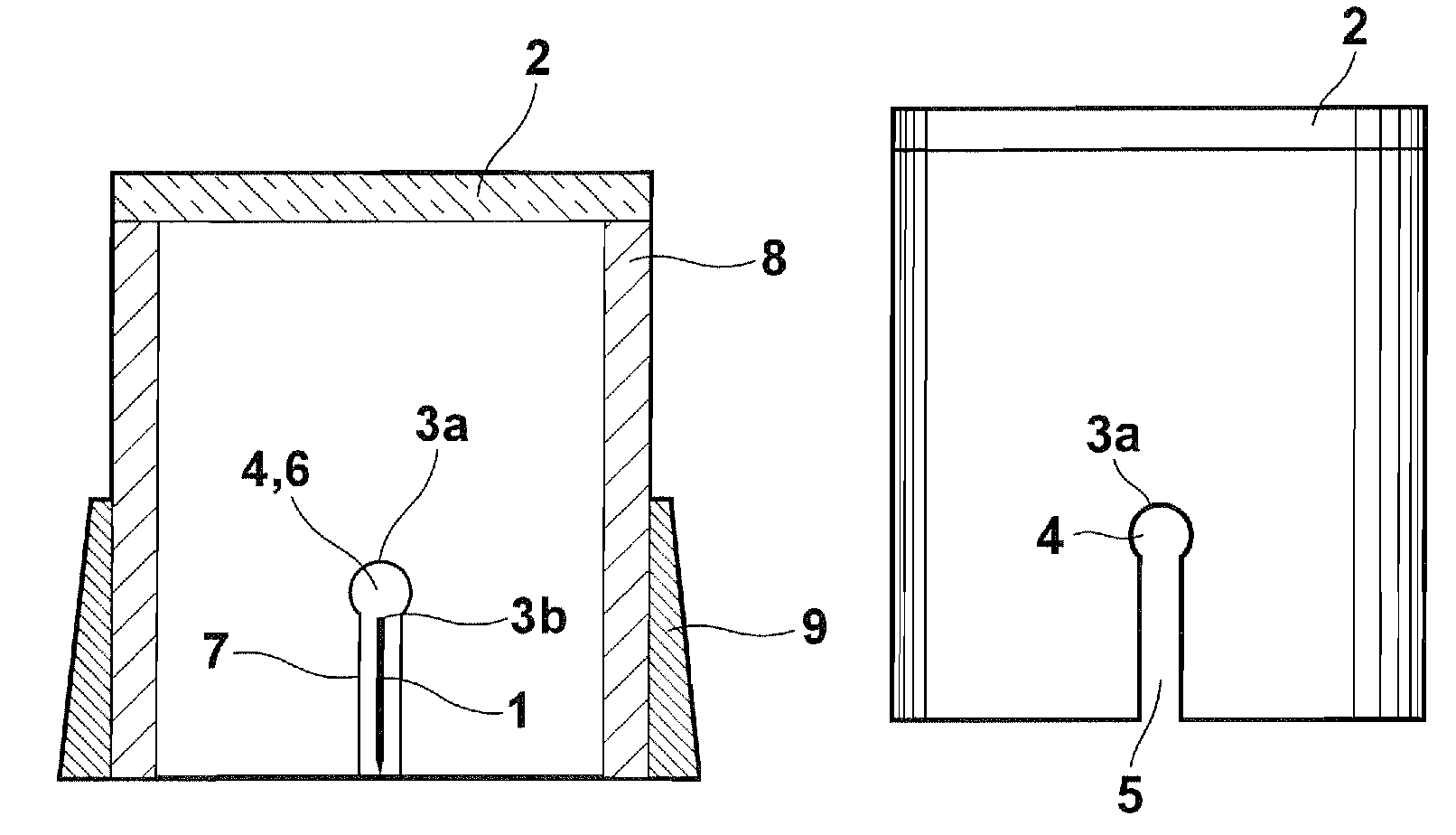
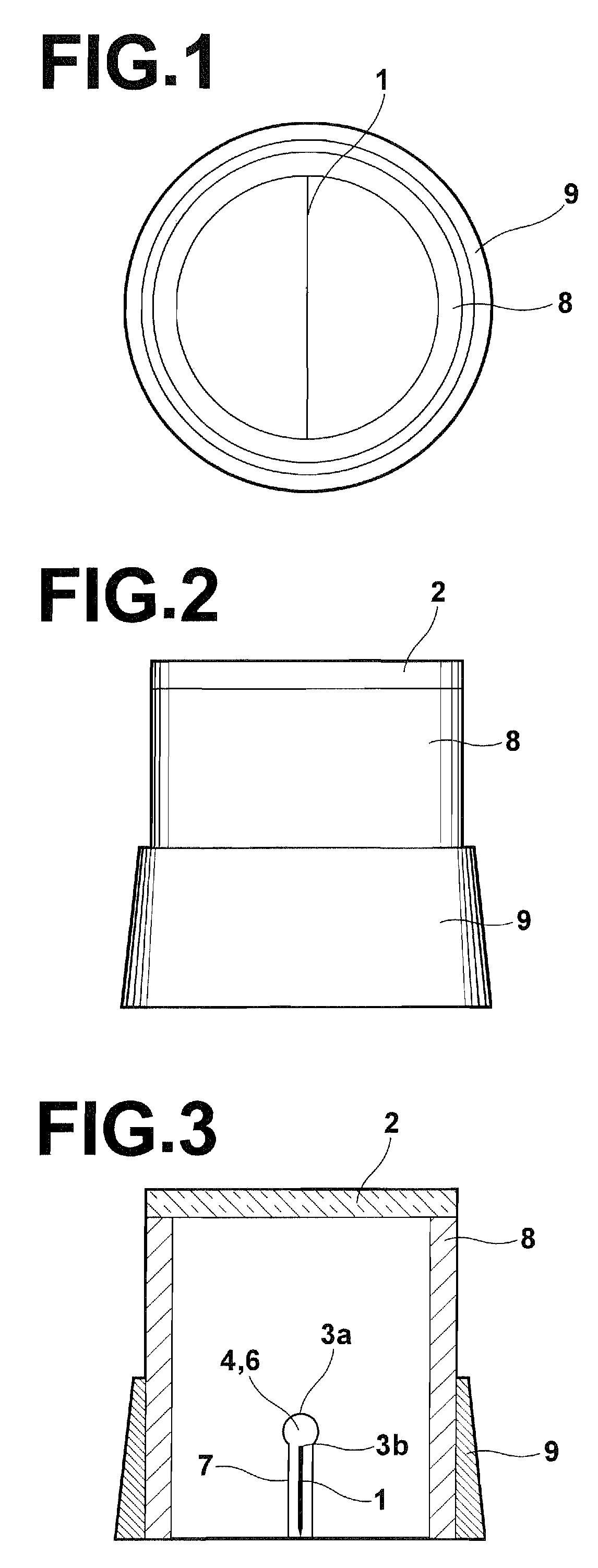
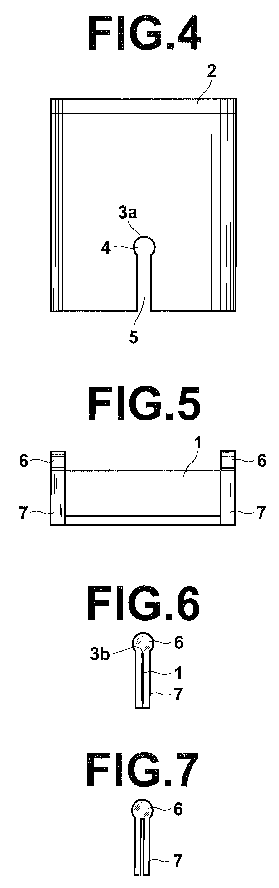
[0019]FIG. 3 shows a vertical cross-section of a tablet cutter in accordance with a preferred embodiment of the present invention. In FIG. 3, the cutting edge fixing part (4, 5 and 6) are shown for the purpose of simplicity. As material of a transparent top plate (2), synthetic resin high in transparency such as acrylic resin, glass or other materials high in transparency, and a magnifying lens formed by these materials can be used. As material of a hollow column (8) and a cover (9), a synthetic resin such as acrylic resin and metal such as aluminum can be used. As material of a cutting edge (1) and the component for fixing the cutting edge shown in FIG. 7, metal having a corrosion-proofness such as stainless steel, a synthetic resin high in hardness such as hard plastics, a ceramics high in hardness, and other hard material can be used.

[0020]In this tablet cutter, a cutting edge (1) ...


PUM


Abstract

A tablet cutter is formed by a cutting edge mounted on the bottom of a hollow column in perpendicular thereto and a transparent top plate mounted on the top of the hollow column to close the top thereof, a convex edge fixing head and an edge bearing head on a concave side surface of the hollow column which conforms to the head so that the contacting area of the head and the edge bearing head to which impact is transferred upon cutting action. The width in a horizontal direction of the edge bearing head and the edge fixing head is larger than that of the edge bearing body and the edge fixing body, and these elements are covered with a cover having an inner diameter equal to the outer diameter of the hollow column.

Description

[0001]This is a continuation of the International Application PCT / JP2005 / 014359, filed on Aug. 8, 2005, which in turn claims the priority benefit of the Japanese Patent Application No. 2004-344880, both priorities are claimed and both applications are incorporated herein by reference.FIELD OF THE INVENTION[0002]This invention relates to a tablet cutter.BACKGROUND OF THE INVENTION[0003]When dividing a tablet with a cutting line into halves, there have been employed scissors, knives, cutters or tablet cutters. When using such tools, the tablet is generally cut in such a manner that the cutting edge of the tool is applied to the cutting line of the tablet in the case of scissors, knives or cutters, while there are some conventional tablet cutters in which the tablet is cut in such a manner that the cutting line of the tablet is applied to the cutting edge of the tool. On the other hand, in the tablet cutter disclosed in Japanese Patent Application No. 2000-95836, the tablet is cut in s...

Claims


Application Information

Patent Timeline
Patent Type & Authority Patents(United States)
IPC IPC(8): B26F3/00
CPCA61J7/0007B26D1/0006B26D3/30B26D2001/006Y10T225/371Y10T225/30
Inventor IWASAKI
Owner IWASAKI
Why Eureka
Try Eureka