Absorbent article with compressed groove and flexible portion

a technology of absorbent articles and grooves, applied in the field of absorbent articles, can solve the problems of lateral leakage or rearward leakage, wearer discomfort, and absorbent articles cannot be kept in close contact with the vaginal opening and the cleft of the buttocks

Inactive Publication Date: 2009-03-17
UNI CHARM CORP
View PDF11 Cites 77 Cited by
  • Summary
  • Abstract
  • Description
  • Claims
  • Application Information

AI Technical Summary

Benefits of technology

[0021]If two grooves in a side-by-side relationship are provided on each side of the article within the above-mentioned range, preferably within a range not overlapping with the flexible portion, stiffness can be increased at right and left sides of the portion intended to face the vaginal opening, so that when a pressure from the thighs is exerted thereon, the portion can be easily pressed against the vaginal opening.
[0023]In this construction, since the portion having the rear flexible portion becomes relatively thin to have a low basis weight, this portion can be easily bent to bulge toward the cleft of the buttocks. On the other hand, since the portion intended to face the vaginal opening becomes relatively thick to have a high basis weight, this portion can be certainly pressed against the vaginal opening without causing bending deformation.
[0025]In this construction, since the absorbent article can be firmly fixed to an undergarment at both sides of the portion intended to face the vaginal opening and at both sides of the rear flexible portion through the pressure-sensitive adhesive layers, a shrinkage force of the undergarment certainly acts on the absorbent article in the vicinity of the lateral reference line, so that the portion along the lateral reference line can be easily brought into close contact with the vaginal opening. In addition, since the absorbent article can be firmly fixed to an undergarment at both sides of the rear flexible portion, the portion having the rear flexible portion can always remain opposed to the cleft of the buttocks without being displaced from the undergarment.

Problems solved by technology

However, such a tight undergarment may possibly make the wearer feel unpleasant due to excessive pressure on her lower body during wear.
Since the absorbent article is so constructed as to be easily folded to decrease its width over almost the whole length, the absorbent article in a folded state is hardly restored to its original flat state, so that the absorbent article cannot be certainly kept in close contact with the vaginal opening and the cleft of the buttocks.
Accordingly, it may possibly fail to collect menstrual blood, causing lateral leakage or rearward leakage.
In addition, since the backside compressed groove extends rearwardly from the center of the absorbent article, if the absorbent article is accidentally worn back to front to have its front portion not having the backside compressed groove opposed to the cleft of the buttocks, the absorbent article cannot closely fit into the cleft of the buttocks.
Therefore, pressure acting on the topside grooves from the thighs cannot be transmitted to the rear groove, so that it is difficult to deform the portion having the rear groove to bulge toward the cleft of the buttocks only by pressure from the thighs.

Method used


Image

  • Absorbent article with compressed groove and flexible portion
  • Absorbent article with compressed groove and flexible portion
  • Absorbent article with compressed groove and flexible portion

Examples


first embodiment

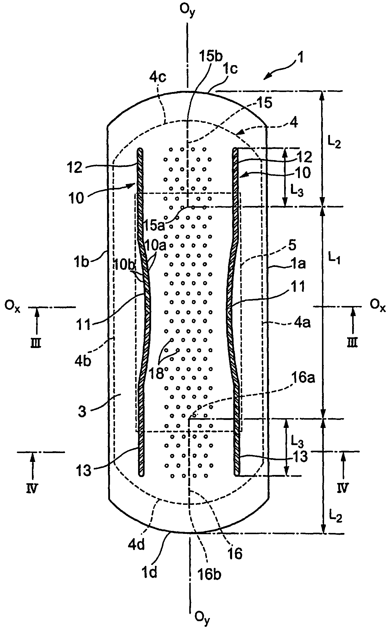
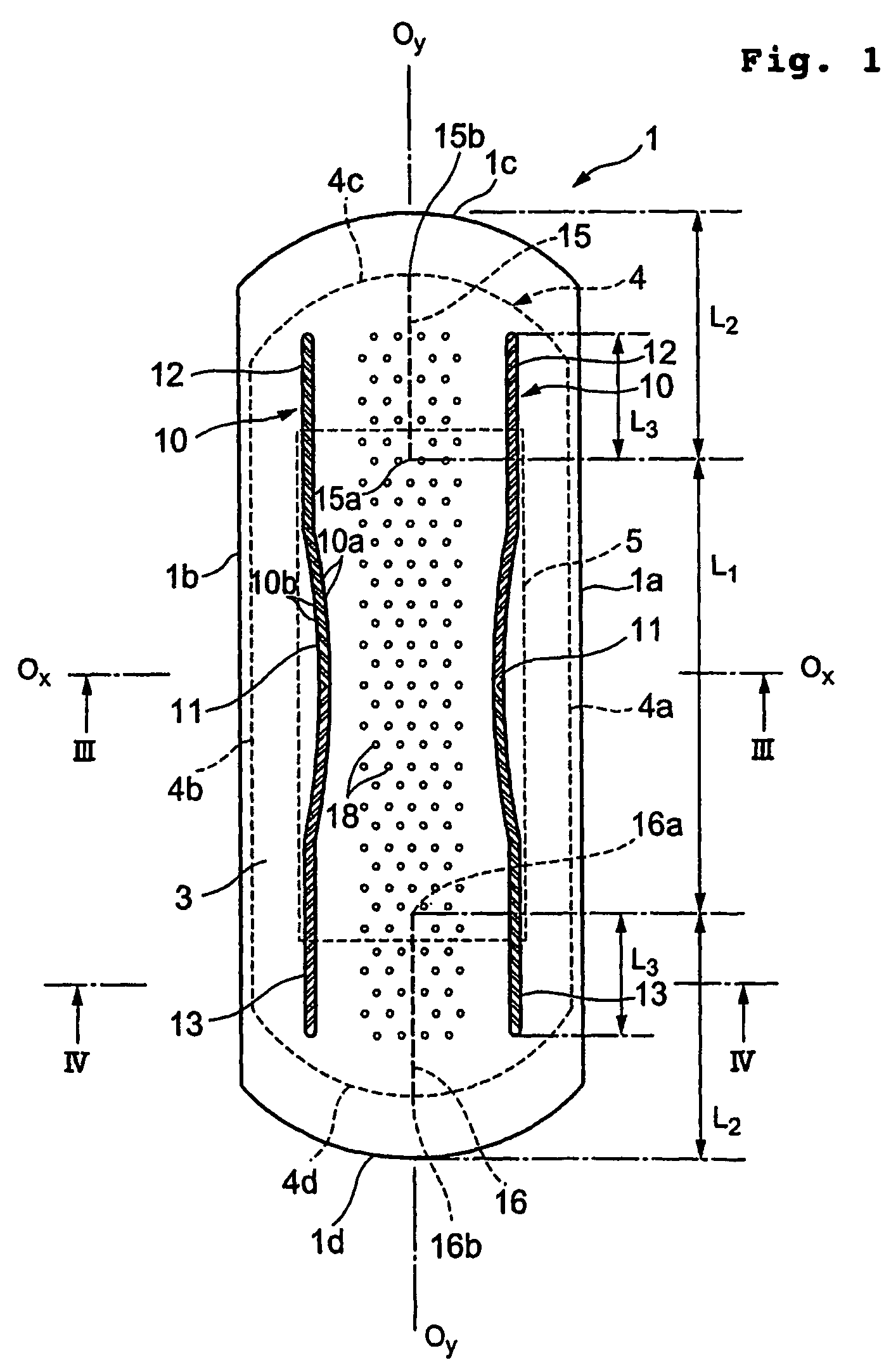
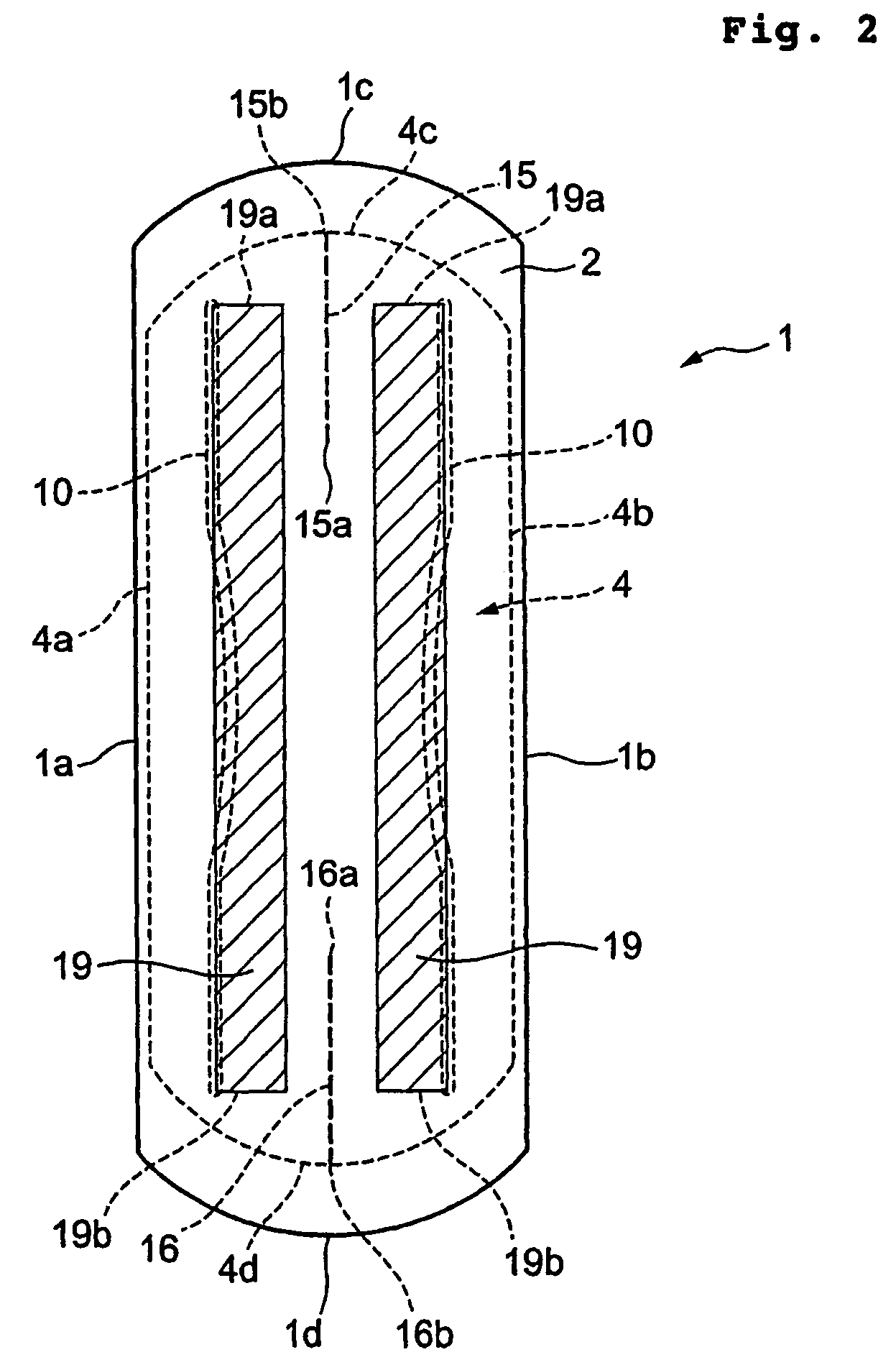
[0042]FIG. 1 is a top plan view showing a sanitary napkin 1 as an absorbent article according to the present invention, wherein the skin surface faces upward; FIG. 2 is a bottom plan view showing the sanitary napkin 1 of FIG. 1, wherein the garment surface faces upward; FIG. 3 is a sectional view of the sanitary napkin 1 taken along line III-III of FIG. 1; and FIG. 4 is a sectional view of the sanitary napkin 1 taken along line IV-IV of FIG. 1.

[0043]The sanitary napkin 1 shown in FIG. 1 is of symmetrical configuration about the longitudinal centerline Oy-Oy and also about the lateral reference line Ox-Ox. Therefore, the sanitary napkin 1 has no difference between front and rear, so that it can be used in the same manner regardless of which one of longitudinally opposed end edges is directed to the abdomen. In the following description, however, one of the longitudinally opposed end edges is referred to as front end edge 1c while the other is referred to as rear end edge 1d, for conv...

second embodiment

[0109]FIG. 6 is a top plan view showing a sanitary napkin 1A as an absorbent article according to the present invention.

[0110]In the sanitary napkin 1A, inner compressed grooves 17, 17 are formed inside the first compressed portions 11, 11 of the compressed grooves 10, 10. The inner compressed grooves 17, 17 are formed in the same manner as the compressed grooves 10, 10, so that the high-density compressed portions 10a and the medium-density compressed portions 10b alternate with each other and the skin surface is recessed toward the garment surface. Preferred ranges of the dimension and density of the inner compressed grooves 17, 17 are identical to those of the compressed grooves 10, 10.

[0111]The inner compressed grooves 17, 17 are formed to extend over substantially the same length as the first compressed portions 11, 11 in the longitudinal direction. The inner compressed grooves 17, 17 are curved toward the longitudinal centerline Oy-Oy. On each side, the center of curvature of ...

third embodiment

[0119]The wings 40, 40 may also be provided in the embodiments shown in FIGS. 1 and 6. Also in the embodiments shown in FIGS. 1 and 6, the flexible portions 15 and 16 may be bifurcated to have the bifurcated flexible portions 15c, 15c and 16c, 16c, respectively. As in the third embodiment, the bifurcated flexible portions 15c, 15c may be continuous with or separated from the flexible portion 15 and the bifurcated flexible portions 16c, 16c may also be continuous with or separated from the flexible portion 16.

[0120]Although the present invention has been illustrated and described with respect to exemplary embodiments thereof, it should be understood by those skilled in the art that the foregoing and various other changes, omission and additions may be made therein and thereto, without departing from the spirit and scope of the present invention. For example, although the sanitary napkins according to the foregoing embodiments are all symmetrical about the lateral reference line Ox-Ox...


PUM


Abstract

Disclosed is an absorbent article including compressed grooves (11) and a rear flexible portion (16). The compressed grooves (11) where a liquid absorbent layer (4) is compressed and recessed from the side of a skin surface toward a garment surface are provided to extend in a longitudinal direction of the article so as to approach each other the nearest on a lateral reference line (Ox-Ox) of the article. The rear flexible portion (16) where the liquid absorbent layer (4) is recessed from the side of the garment surface toward the skin surface is provided to extend toward a rear end edge (1d) from a starting point (16a) that is located closer to the rear end edge (1d) than the lateral reference line (Ox-Ox). At least a portion of the rear flexible portion (16) is located between the compressed grooves (11).

Description

CROSS REFERENCE TO THE RELATED APPLICATION[0001]The present application has been filed with claiming priority based on Japanese Patent Application No. 2002-381564, filed on Dec. 27, 2002. Disclosure of the above-identified Japanese Patent Application is herein incorporated by reference.TECHNICAL FIELDS[0002]The present invention relates to an absorbent article suitable for absorbing menstrual blood and so on discharged from a woman's genital organ, more particularly, relates to an absorbent article that can easily conform to the vaginal opening and the cleft of the buttocks.BACKGROUND ART[0003]Absorbent articles intended to absorb menstrual blood discharged from a woman's genital organ are typically constructed to include a liquid absorbent layer, a liquid-permeable topsheet covering the skin surface of the liquid absorbent layer, and a liquid-impermeable backsheet covering the garment surface of the liquid absorbent layer, and generally, they are worn with the backsheet adhered to ...

Claims


Application Information

Patent Timeline
Patent Type & Authority Patents(United States)
IPC IPC(8): A61F13/15A61F13/20A61F13/49A61F13/511A61F13/53A61F13/539
CPCA61F13/4704A61F13/4756A61F13/47218A61F13/53A61F13/533A61F13/15
Inventor TAMURA, TATSUYAMIZUTANI, SATOSHISUEKANE, MAKOTOKOMATSU, SHIMPEI
Owner UNI CHARM CORP
Why Eureka
Try Eureka