Automatic take-up device with internal spring

a technology of automatic take-up and internal spring, which is applied in the direction of threaded fasteners, load-modified fasteners, screws, etc., can solve the problems of wood shrinkage, loss of moisture, and loss of tension of rods, and achieves strong mechanical connection, less likely to fail, and resistant to shaking and vibration

Inactive Publication Date: 2009-03-31
SIMPSON STRONG TIE
View PDF139 Cites 14 Cited by
  • Summary
  • Abstract
  • Description
  • Claims
  • Application Information

AI Technical Summary

Benefits of technology

[0011]It is an object of the present invention to provide an expansion device for a tie down connection system that operates to assure continued tightness and rigidity in a connection system.
[0015]It is a further object of the present invention to provide an expansion member that is strong and can adequately transmit forces from one working member at one end of the device to another working member at the other end of the device. The preferred embodiment uses two threaded cylindrical bearing members that mate with the thread of the surrounding sleeve. The threaded connection between the components creates a strong mechanical connection that is resistant to shaking and vibration.
[0017]It is a further object of the present invention to provide a compact expansion device that can be used with tie down brackets that can be placed within 2×4-framed walls. This benefit is accomplished in part by the use of the threaded connection between the cylindrical bearing members and the sizing sleeve. The threads of the cylindrical bearing member create an adequate bearing and force transmission surface while providing the device with a small footprint.
[0018]It is a further object of the invention to provide a device that is easily installed and incorporated into present building practices. The present invention is easily slipped over a rod or bolt before a nut and washer are tightened down.

Problems solved by technology

However, a number of different factors can cause the nut to move away from the bolt, which causes the rod to lose its tension.
One such factor is wood shrinkage.
However, once the envelope of the building is completed, the lumber is no longer exposed to the relatively humid outside air, and it begins to lose moisture which leads to shrinkage.

Method used


Image

  • Automatic take-up device with internal spring
  • Automatic take-up device with internal spring
  • Automatic take-up device with internal spring

Examples


Embodiment Construction

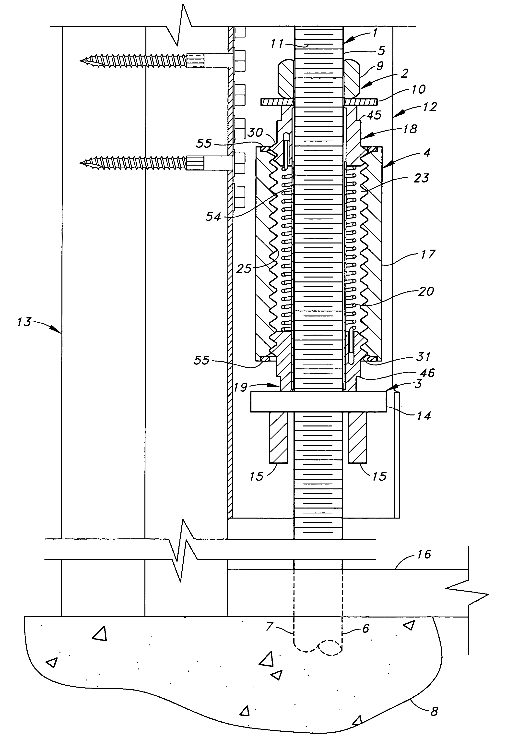
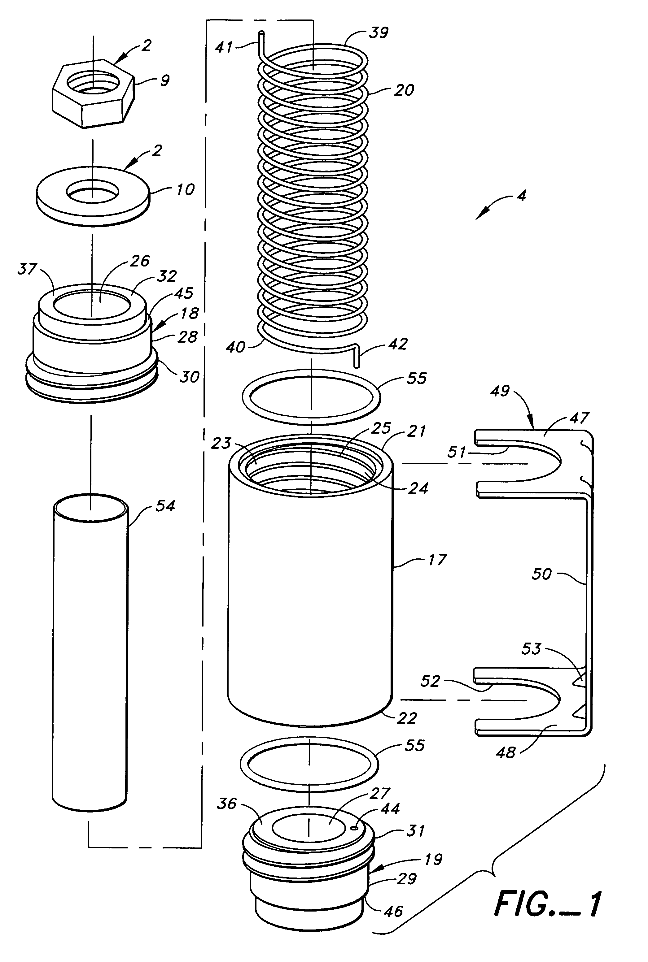
[0038]As shown in FIGS. 4A, 4B and 5A, the present invention relates to a connection between an elongated tension member 1, a fastening member 2 attached to the elongated tension member 1, a resisting member 3 that receives the elongated tension member 1 and an expansion device 4 disposed between the fastening member 2 and the elongated tension member 1.

[0039]The elongated tension member 1 has first and second ends 5 and 6 with the second end 6 being anchored. For example, said elongated tension member 1 could be a threaded anchor bolt 7 with its second or lower end 6 embedded in the concrete foundation 8 of a building. Preferred anchor bolts 7 for embedment in a concrete foundation 8 to be used in the present connection are SSTB anchor bolts.

[0040]The fastening member 2 is attached to the first end 5 of the elongated tension member 1. The fastening member 2 need not be attached at any particular location on the elongated tension member 1, reference is made to the first and second e...


PUM


Abstract

The present invention consists of a connection, having an anchored, elongated tension member, a fastening member attached to the elongated tension member, a resisting member that receives the elongated tension member and an expansion device that receives the elongated tension member there through and is compressively loaded between the fastening member and the resisting member by operation of the fastening member on the elongated tension member. The expansion device is formed with a sleeve. First and second bearing members are received in the central aperture of the surrounding sleeve and operatively connected to the surrounding sleeve. At least one of the bearing members is threadably connected to the sleeve. This bearing member can rotate in relation to the surrounding sleeve.

Description

BACKGROUND[0001]The present invention relates to an expansion device. The device is adapted for maintaining the compression forces one work piece exerts on another. The present invention is inserted between two work pieces and is designed to expand if conditions cause the two to spread apart.[0002]The present invention is particularly suited for use with tie-down systems used to anchor wood-framed buildings to their foundations. Many such systems use a rod or bolt that is anchored at its lower end to either a lower member of the building or directly to its foundation. The upper end of the bolt or rod is connected to a plate or bracket which, in turn, is connected to an upper portion of the building. The rod or bolt is usually connected to the bracket by means of a nut thread onto the bolt or rod that presses against the plate or bracket. The rod or bolt is placed in tension by tightening the nut against the plate or bracket that receives the rod or bolt.[0003]For the rod or bolt to ...

Claims


Application Information

Patent Timeline
Patent Type & Authority Patents(United States)
IPC IPC(8): E02D35/00E02D27/00E04B1/00E04B1/38F16B31/04F16B39/02
CPCE04B1/0007Y10S411/917Y10T74/19902E04B2001/2688
Inventor LEEK, WILLIAM F.
Owner SIMPSON STRONG TIE
Why Eureka
Try Eureka