UAV recovery system II

a technology for uavs and recovery systems, applied in the field of systems for retrieving unmanned aerial vehicles, can solve the problems of difficult to safely land a uav on the deck of a ship, difficult to recover a uav on the ship deck, and rarely attempted deck landings, and achieve the effect of positive capture of the uav

Inactive Publication Date: 2009-03-31
LOCKHEED MARTIN CORP
View PDF12 Cites 94 Cited by
  • Summary
  • Abstract
  • Description
  • Claims
  • Application Information

AI Technical Summary

Benefits of technology

[0015]For use in recovery operations, the boom is rotated from its stowed position to an active position in which it extends over the side of the ship. To recover a UAV, the UAV is flown over the boom such that its direction of flight is substantially orthogonal to the boom and facing the mouth of the grooves in the capture plate. The UAV is flown at an altitude such that mass that is attached to the tail of the UAV is lower than the capture plate. With continued forward motion, the cord that hangs from the UAV is captured by one of the grooves in the capture plate. The UAV continues along a substantially level flight path until the mass / cord is seized at the pinch point of the groove. Since the mass is larger than the groove that is formed between adjacent teeth in the capture plate, a “geometrical” lock results, thereby assuring positive capture of the UAV.

Problems solved by technology

Recovery is considerably more challenging, however, when the UAV is operating at sea.
Due to the constant sway, roll, pitch, and yaw of a ship at sea, it is quite difficult to safely land a UAV on the deck of a ship.
In fact, deck landings are rarely attempted.
This technique has its own drawbacks, including a reasonable likelihood of damage to the UAV and some risk to the recovery crew.
In particular, one drawback is that the apparatus disadvantageously requires a substantial amount of deck area.
A second drawback is that a relatively labor-intensive untangling operation is required to free the UAV from the net.
Furthermore, the relatively abrupt stop of a UAV in the recovery net can damage its fragile wings.

Method used


Image

  • UAV recovery system II
  • UAV recovery system II
  • UAV recovery system II

Examples


Embodiment Construction

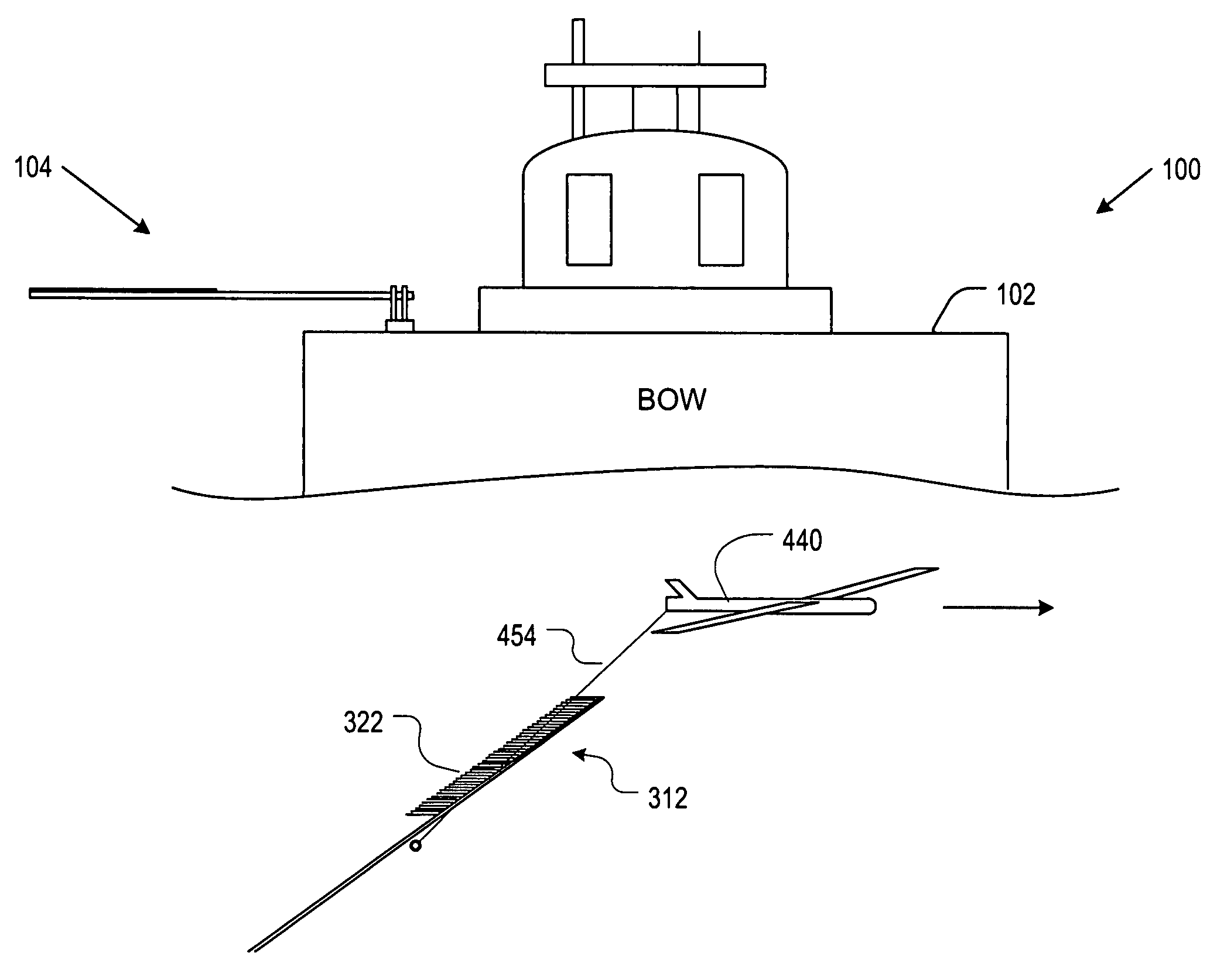
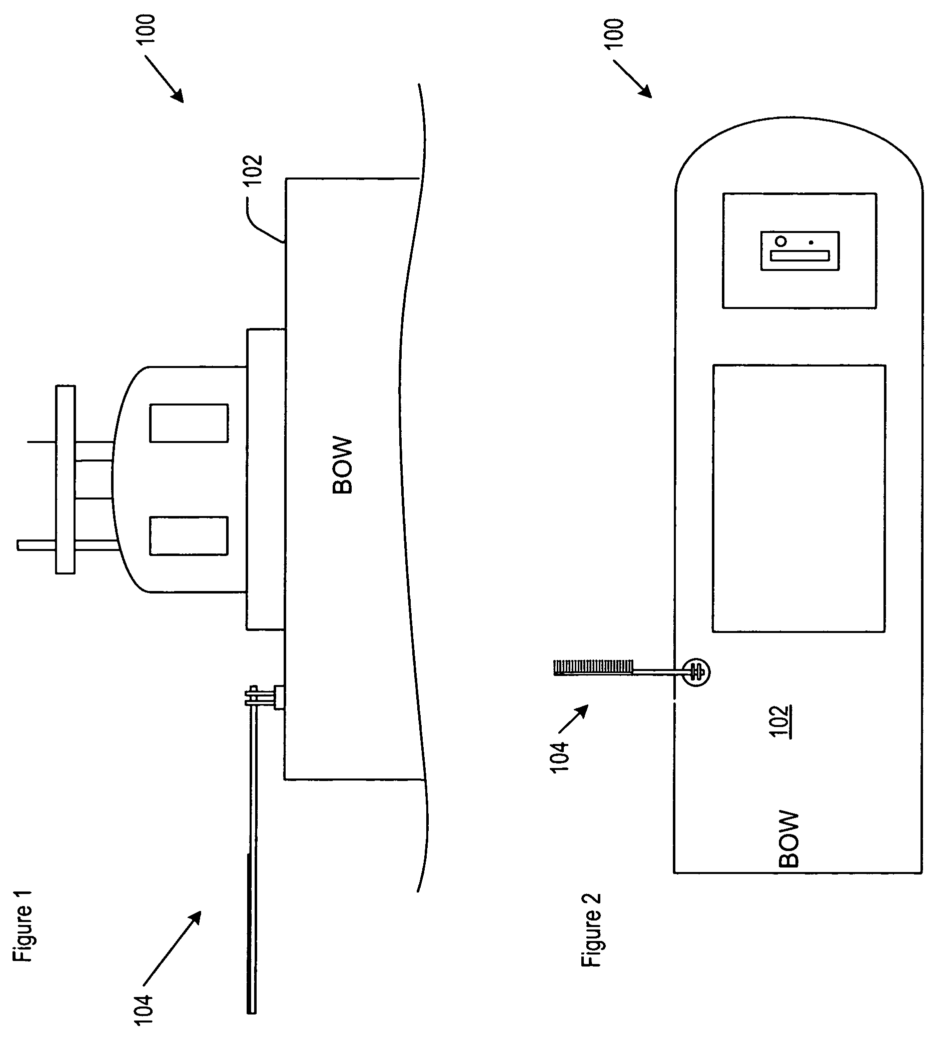
[0025]FIGS. 1 and 2 depict, via respective bow and top views, ship 100. Coupled to deck 102 of the ship are ship-based elements 104 of a UAV recovery system in accordance with the illustrative embodiment of the present invention.

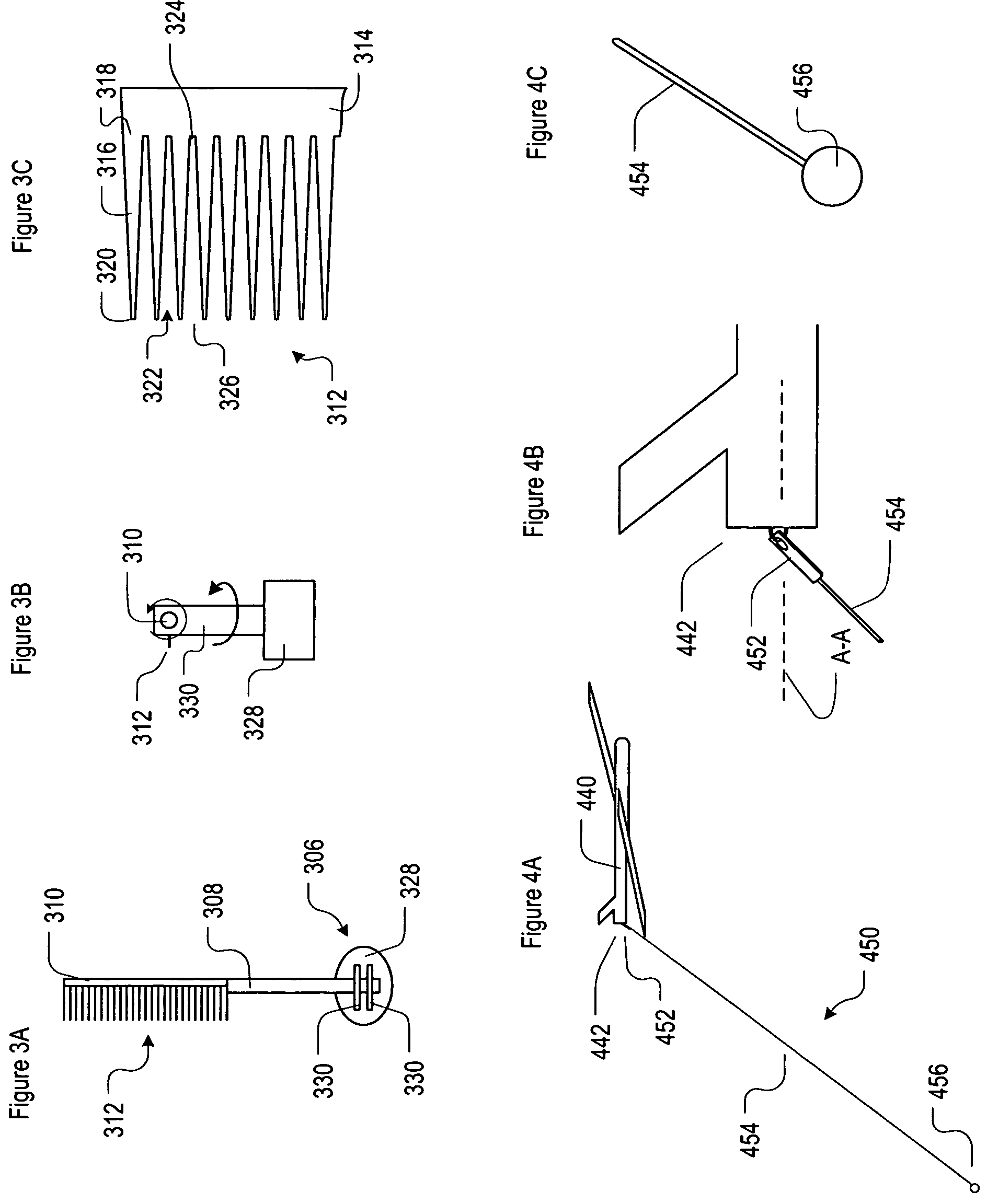
[0026]FIGS. 3A through 3C depict further detail of ship-based elements 104 of the UAV recovery system. Referring now to FIGS. 3A, ship-based elements 104 include support structure 306, movable boom 308, and capture plate 312, which are mechanically interrelated as shown. In the embodiment depicted in FIGS. 3A and 3B, support structure 306 comprises base 328 and upright member(s) 330. In some embodiments, support structure 306 is disposed on an ISO module (not depicted).

[0027]Support structure 306 supports boom 308. As depicted by the arrows in FIG. 3B, the boom is supported in such a way that it has two degrees of freedom. In particular, boom 308 is capable of being rotated about its horizontal long axis (the long axis is directed “into the page” in FIG. 3B)...


PUM


Abstract

A UAV recovery system is disclosed. In the illustrative embodiment for UAV recovery over water, the system includes ship-based elements and UAV-based elements. The UAV-based elements include a mass, such as ball, that is coupled to cord, which is in turn coupled to the tail of a UAV. The ship-based elements include a capture plate and a boom, wherein the boom is pivotably coupled to the deck of a ship. For use in recovery operations, the boom is rotated so that it extends over the side of the ship. A UAV is flown over the boom toward the capture plate at an altitude such that the mass that is attached to the tail of the UAV hangs lower than the capture plate. With continued forward motion, the cord that hangs from the UAV is captured by a grooves in the capture plate. The capture plate geometrically constrains the mass, thereby assuring positive capture of the UAV.

Description

STATEMENT REGARDING FEDERALLY SPONSORED RESEARCH OR DEVELOPMENT[0001]The U.S. Government has a paid-up license in this invention and the right in limited circumstances to require the patent owner to license others on reasonable terms as provided for by the terms of Contract No. N00014-03-C-0408 awarded by the U.S. Government.FIELD OF THE INVENTION[0002]The present invention relates to systems for retrieving unmanned aerial vehicles (“UAVs”).BACKGROUND OF THE INVENTION[0003]The UAV is now widely used for reconnaissance. Characteristically small, inexpensive, and pilot-less (i.e., unmanned cockpit), the UAV is ideal for that purpose.[0004]Notwithstanding its,low cost, the UAV is not considered to be a disposable asset; recovery is at least attempted after each mission. Recovery is relatively straightforward when the UAV is operating over land. In such situations, the UAV is simply brought down on a makeshift landing field. Recovery is considerably more challenging, however, when the U...

Claims


Application Information

Patent Timeline
Patent Type & Authority Patents(United States)
IPC IPC(8): B64F1/02
CPCB64F1/02B64C2201/182B64F1/0297B64U70/30
Inventor SNEDIKER, JOHN
Owner LOCKHEED MARTIN CORP
Why Eureka
Try Eureka