Electrical connector having improved based element

a technology of a base element and an electrical connector, which is applied in the direction of coupling devices, two-part coupling devices, electrical apparatus, etc., can solve the problems of unstable structure and complicated manufacture of electrical connectors, and achieve the effect of mating with a terminal module easily and firmly

Active Publication Date: 2009-03-31
HON HAI PRECISION IND CO LTD
View PDF4 Cites 29 Cited by
  • Summary
  • Abstract
  • Description
  • Claims
  • Application Information

AI Technical Summary

Benefits of technology

[0007]One object of the present invention is to provide an electrical connector having an improved base element adapted for mating with a terminal module easily and firmly.
[0009]Thus, the terminal module is easy to be mounted into the cutout and firmly fixed in the cutout by the interference between the passage of the insulative insert and the inner edge of the cutout of the base element.

Problems solved by technology

However, the electrical connector defines two grooves at the front sides of the left and the right base parts to assemble the two connecting pin sets, that would complicate the manufacture of the electrical connector and render the structure unstable.

Method used


Image

  • Electrical connector having improved based element
  • Electrical connector having improved based element
  • Electrical connector having improved based element

Examples


Embodiment Construction

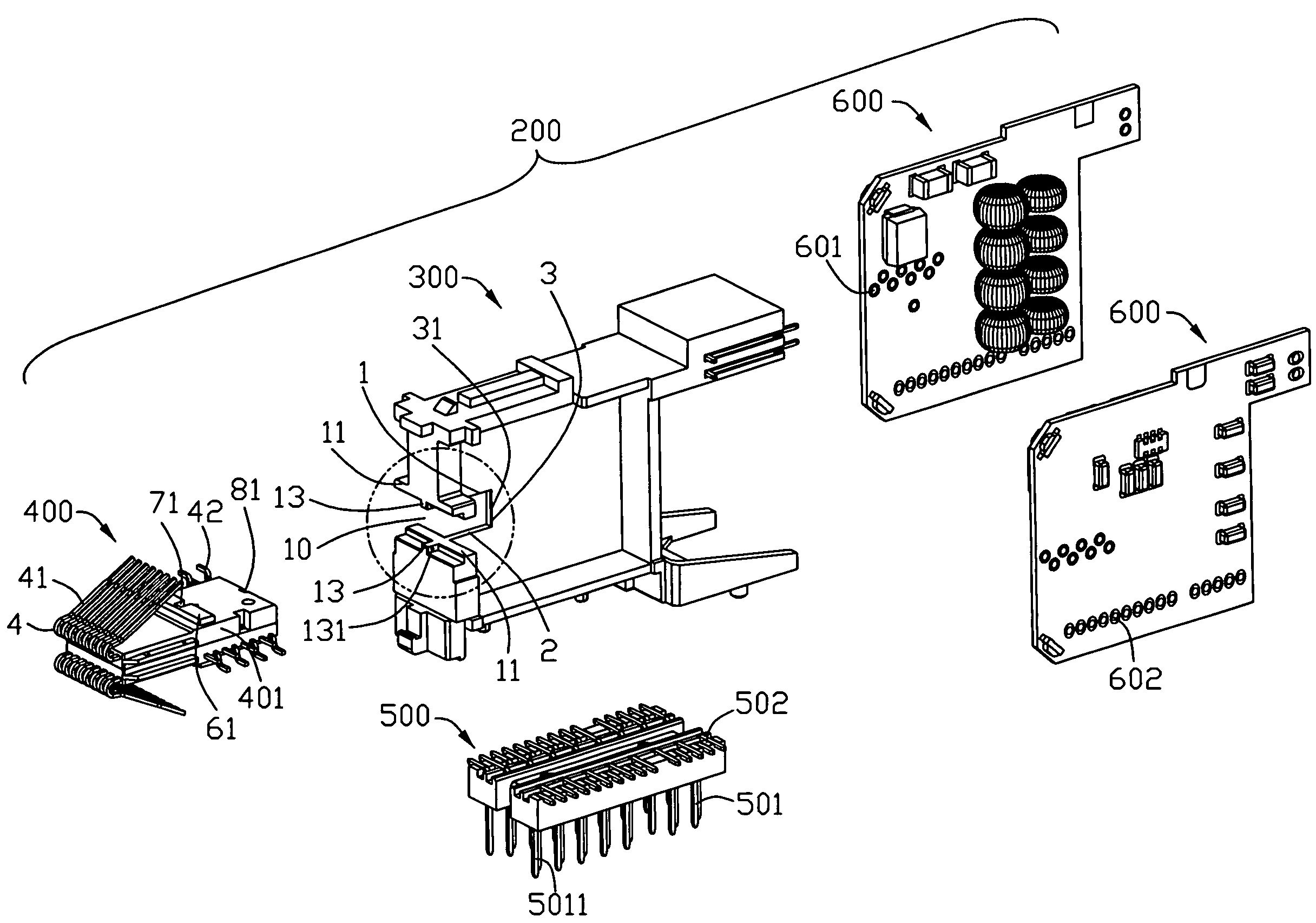
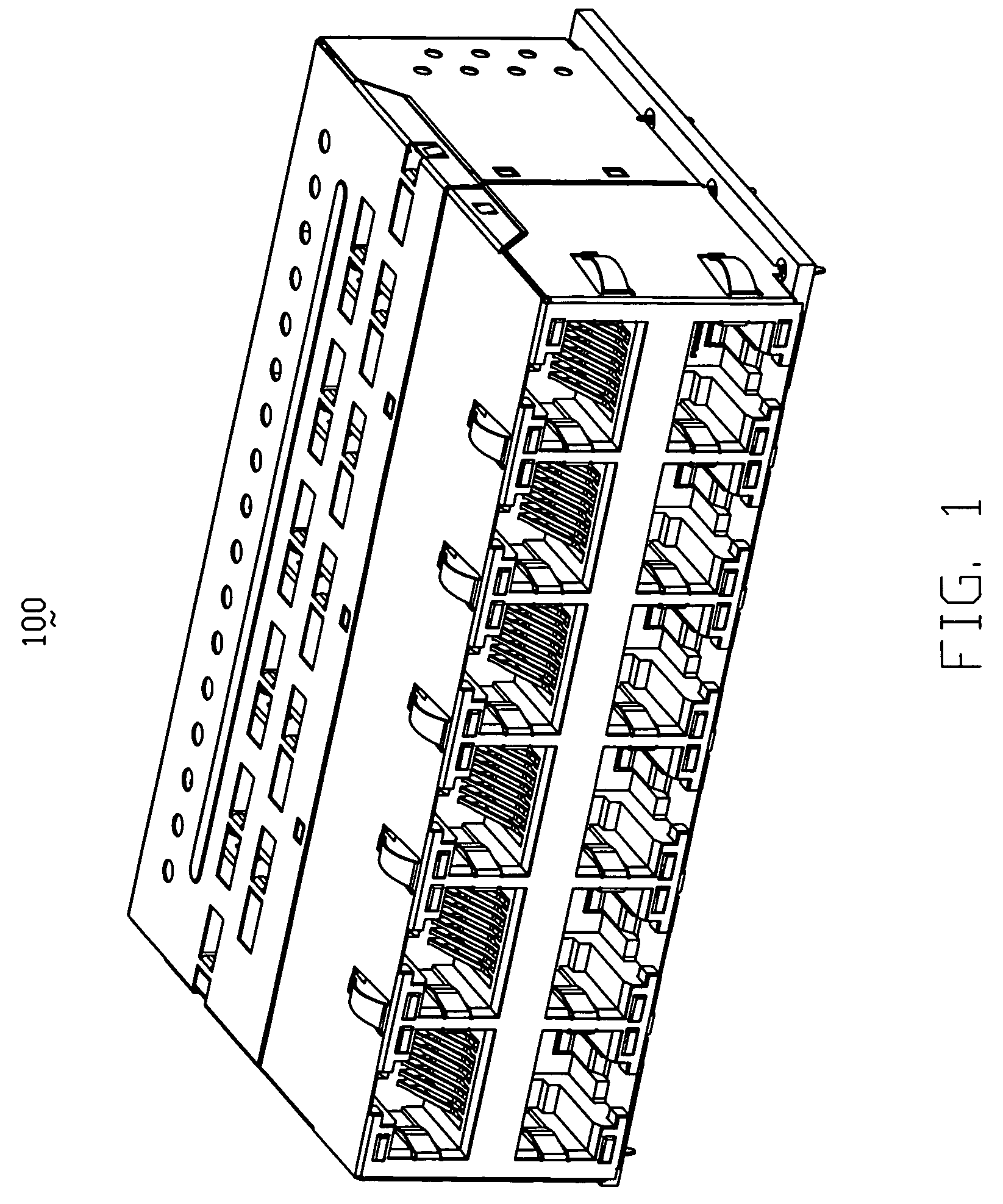
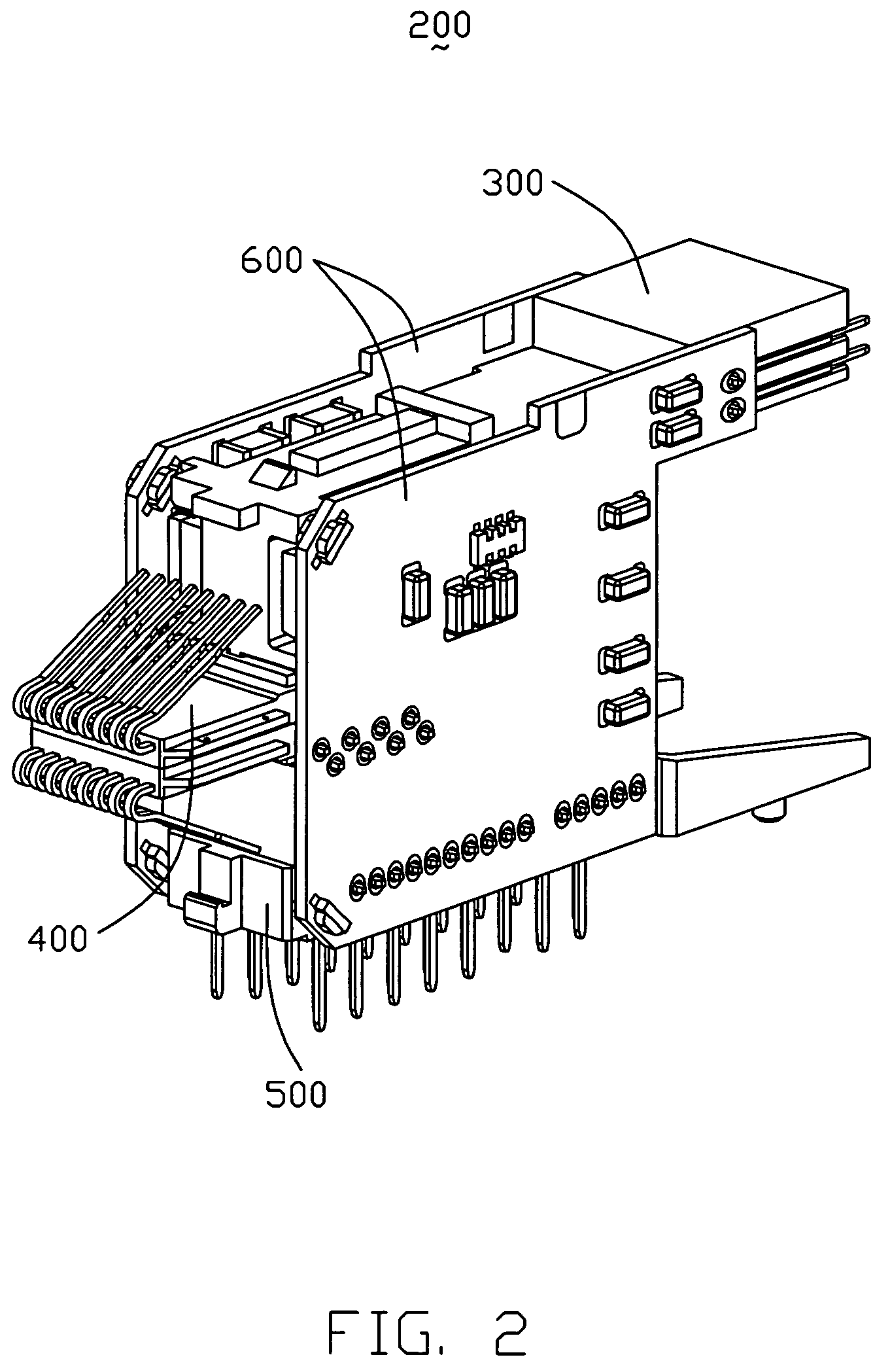
[0018]Reference will now be made to the drawing figures to describe the present invention in detail. Referring to FIGS. 1-3, an electrical connector 100 for engaging with a mating plug (not shown) comprises a base element 300, a terminal module 400 mounted to the base element 300, a pair of daughter boards 600 attached to opposite side faces of the base element 300 and a spacer 500 mounted below the base element 300. The terminal module 400 includes an insulative insert 401 and two groups of terminals 4 mounted to the insulative insert 401.

[0019]As shown in FIGS. 4-7, the base element 300 has a pair of opposite contacting portions 301 respectively disposed on a front section 30 thereof and a cutout 10 defined between the pair of contacting portions 301. The front section 30 has a top wall 1, a bottom wall 2 and a rear wall 3. The cutout 10 is configured to cooperate with the terminal module 400 with an inner edge 31 disposed on the rear wall 3 for engaging to a corresponding passage...


PUM


Abstract

An electrical connector (200) for engaging with a mating plug includes a terminal module (400) having an insulative insert (401) and rows of terminals (4) mounted to the insulative insert, a base element (300) and a daughter board (600) attached to a side face of the base element. The base element has a pair of opposite contacting portions (301) disposed on a front section thereof and a cutout (10) defined between the pair of contacting portions. The cutout is configured to cooperate with the terminal module with an inner edge (31) engaging to a corresponding passage (81) defined on a rear face of the insulative insert.

Description

BACKGROUND OF THE INVENTION[0001]1. Field of the Invention[0002]The present invention relates to an electrical connector and particularly to electrical connector comprising an improved base element for engaging with a terminal module.[0003]2. Description of the Prior Art[0004]A U.S. Pat. No. 7,134,915 issued on Dec. 14, 2006 discloses an electrical connector. The electrical connector engaging with a mating plug comprises a left and a right base part mutually connecting and symmetrically arranged and a plurality of terminals embedded therein and extended outwardly to be connected circuit board. The electrical connector has two connecting pin sets mutually and conversely mounted to the left and right base part. The left and right base parts respectively has bending portion extending from a bottom of said left base part and a top of right base part, thus forming two grooves for coupling with the connecting pin sets.[0005]However, the electrical connector defines two grooves at the fron...

Claims


Application Information

Patent Timeline
Patent Type & Authority Patents(United States)
IPC IPC(8): H01R13/66
CPCH01R13/514H01R13/6658H01R24/64
Inventor ZHANG, HONG-BOXU, ZHENG-HUAWU, LI-CHUN
Owner HON HAI PRECISION IND CO LTD
Why Eureka
Try Eureka