Power connector with light indicator

a technology of power connector and light indicator, which is applied in the direction of electrical apparatus, connection, coupling device connection, etc., can solve the problem of difficult identification of transmission faults

Inactive Publication Date: 2007-01-30
HON HAI PRECISION IND CO LTD
View PDF13 Cites 27 Cited by
  • Summary
  • Abstract
  • Description
  • Claims
  • Application Information

AI Technical Summary

Benefits of technology

[0006]Accordingly, the object of the present invention is to provide a power connector with a light indicator indicating the working status of the power connector.

Problems solved by technology

However, conventionally, it is difficult to identify such transmission fault, since no indicating device is employed or indicating device can not be seen obviously.

Method used


Image

  • Power connector with light indicator
  • Power connector with light indicator
  • Power connector with light indicator

Examples


Embodiment Construction

[0018]Reference will now be made in detail to the preferred embodiment of the present invention.

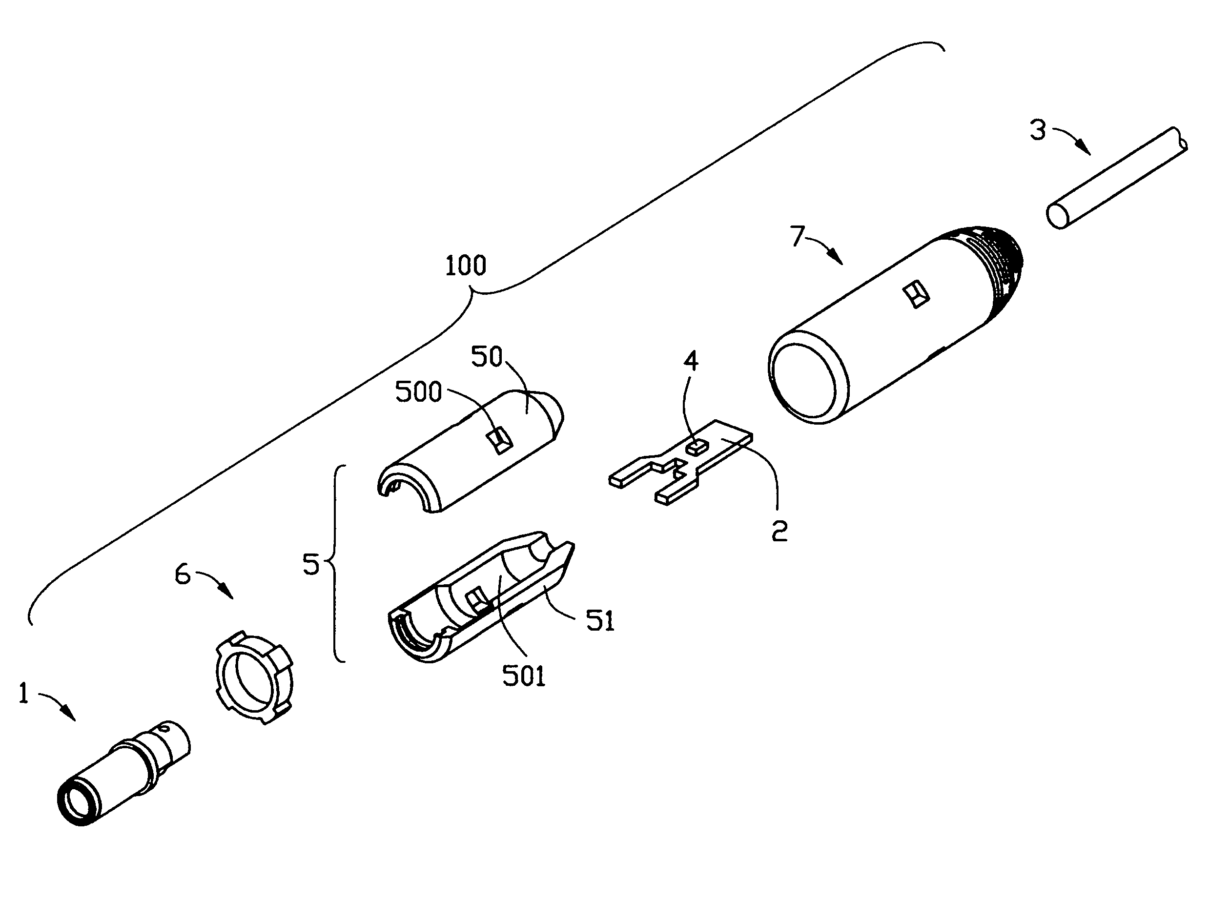
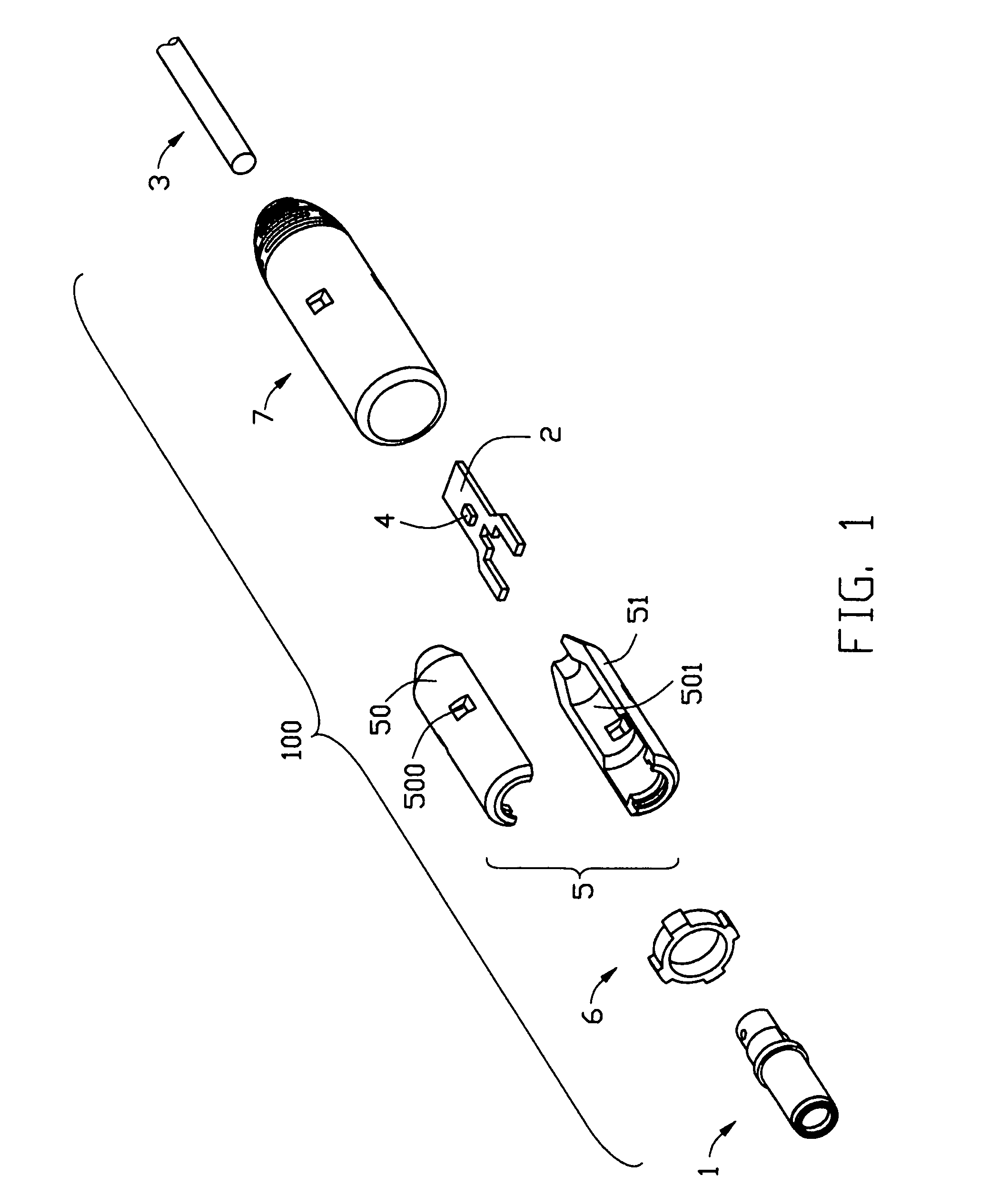
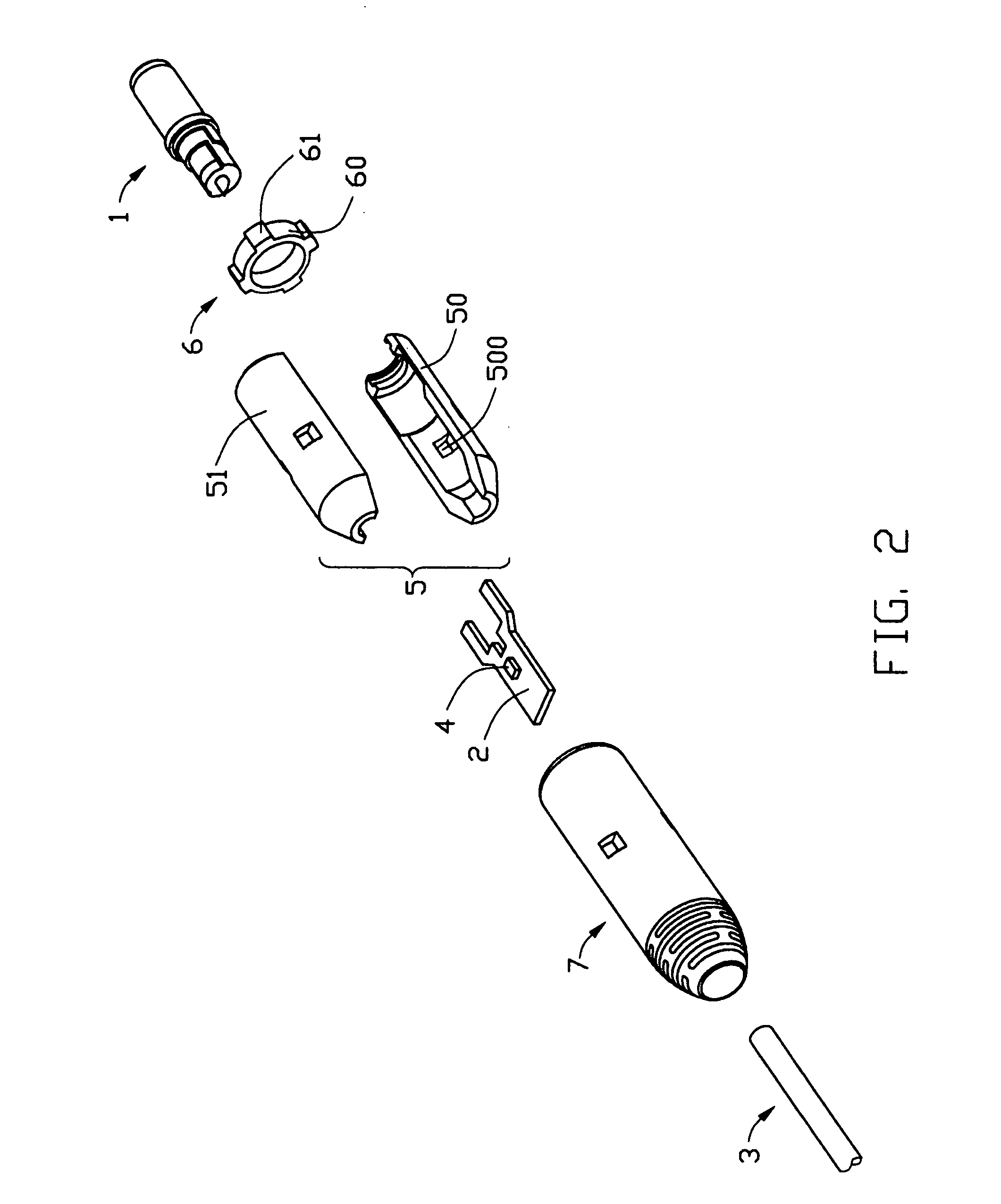
[0019]referring to FIG. 1 and FIG. 2, a power connector 100 in accordance with the first embodiment of the present invention comprises a mating plug 1, a circuit board 2 connected to the mating plug 1, a cable 3 having a plurality of conductors (not shown) electrically connected with the circuit board 2, a light-emitting diode (LED) 4 assembled to the circuit board 2, a hollow column inner insulator 5, a light pipe 6 attached to inner face of the inner insulator 5 and an insulative outer cover 5 covering the inner insulator 5. The light-emitting diode 4 and the light pipe 6 together form a light indicator of the power connector 100 to indicate the working status of the power connector 100.

[0020]Referring to FIG. 3 to FIG. 5, the mating plug 1 is connected to the circuit board 2 in a jumper manner. The mating plug 1 comprises a cylindrical dielectric housing 10, a center signal terminal 11...


PUM


Abstract

A power connector (100) can mate with a complementary connector and includes a mating plug (1) matable with the complementary connector, a circuit board (2) connected to the mating plug, a light-emitting diode (4) assembled to the circuit board to indicate working status of the power connector and a light pipe (6) transmitting the light from light-emitting diode. The mating plug includes first and second terminals (12, 13) for power transmission.

Description

BACKGROUND OF THE INVENTION[0001]1. Field of the Invention[0002]The present invention relates to an electrical connector, and more particularly to a power connector for power transmission.[0003]2. Description of Related Art[0004]Power jacks / plugs are widely used in the electrical industry to connect power supplies with electrical devices, such as mobile phone, note book. The power jack generally is mouted to a Printed Circuit Board (PCB). The power plug is connectable with a cable and comprises a dielectric housing, an inner contact and an outer contact respectively served as a positive pole and a negative pole of a power supply for powering electrical device connecting to the power connector, and a signal contact provided for signal transmission. In mating, a current flowing between the power plug and the PCB to which the power jack is mounted is achieved. To assure stable electrical connection between the power plug and the PCB, it is necessary to equip the power plug with an indi...

Claims


Application Information

Patent Timeline
Patent Type & Authority Patents(United States)
IPC IPC(8): H01R3/00
CPCH01R13/6658H01R13/641
Inventor KUO, PETER
Owner HON HAI PRECISION IND CO LTD
Why Eureka
Try Eureka