RF coil identification and testing interface for NMR systems

a technology of rf coils and interface systems, applied in the field of radio frequency coil front end interface systems for magnetic resonance scanners, can solve the problems of injuring patients, complex management of multiple analog conductor cables, and incorrect indication of the nature of installed coils by computers, so as to simplify the use of the system, prevent the operation of defective coils and prevent the operation of coils in inappropriate modes.

Inactive Publication Date: 2000-01-11
PICKER INT
View PDF5 Cites 26 Cited by
  • Summary
  • Abstract
  • Description
  • Claims
  • Application Information

AI Technical Summary

Benefits of technology

One advantage of the present invention resides in patient safety. Operation of defective coils and operation of coils in an inappropriate mode are prevented.
resides in patient safety. Operation of defective coils and operation of coils in an inappropriate mode are prevented.
Another advantage of the present invention is that it simplifies use of the system. Coil identifications and malfunctioning coil warnings are provided to the operator. Remote operator selection of authorized coil modes can be made without moving the patient or entering the scan room.
Another advantage of the present invention is that patients and coils can be positioned automatically without laser alignment and gauging procedures.
Still further advantages of the present invention will become apparent to those of ordinary skill in the art upon reading and understanding the following detailed description of the preferred embodiments.

Problems solved by technology

One disadvantage of this system is that it is very complex to manage a multiple analog conductor cable because it is large and prone to pick up stray radio frequency signals.
Moreover, when one of the wires or contacts fails, an incorrect indication of the nature of the installed coil is provided to the computer.
This erroneous indication of the installed coil could cause an imaging sequence to be initiated which could injure the patient or cause damage to the magnetic resonance equipment.
One drawback of this system is that it provides no direct indication of coil failure.
The large reflected power may cause the RF amplifier to shut down in one of its fault modes.
One drawback to this type of system is that it complicates the connector because extra pins arc needed for identifying the coil type.
The system has no check of the level of current in the coil and could indicate an incorrect type of coil.
Further, there is no check that the coil is, in fact, functioning in the identified mode.

Method used


Image

  • RF coil identification and testing interface for NMR systems
  • RF coil identification and testing interface for NMR systems
  • RF coil identification and testing interface for NMR systems

Examples


Embodiment Construction

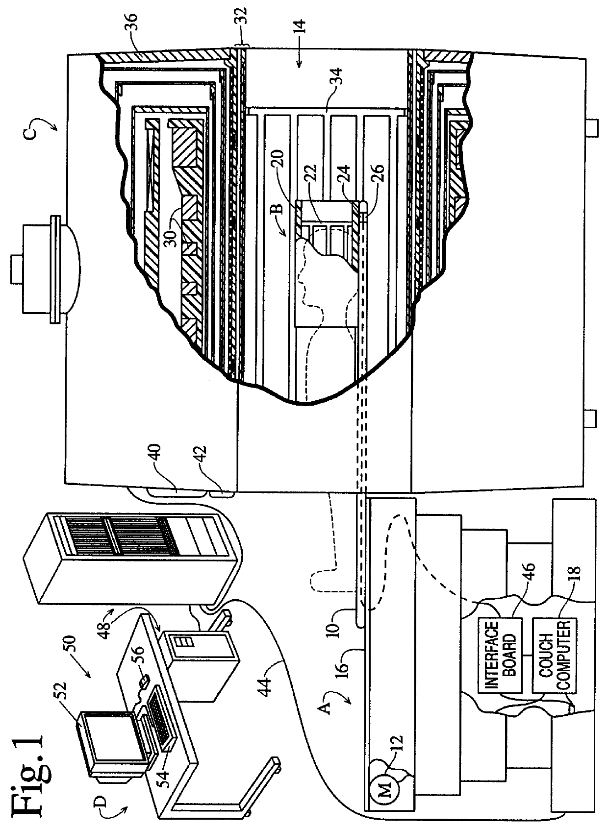
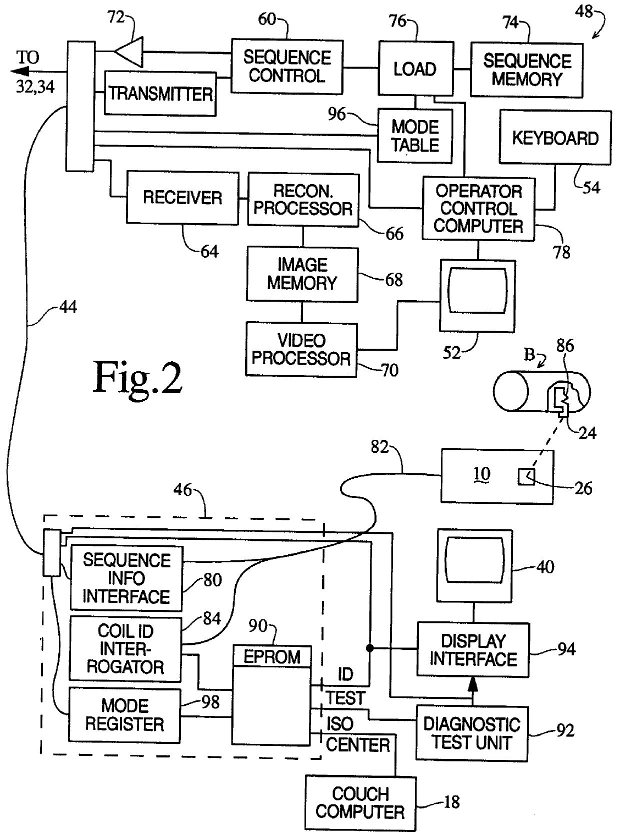
With reference to FIG. 1, a patient couch assembly A selectively inserts and retracts a patient and a localized coil assembly B into and out of an examination region of a cryogenic magnet unit C. The patient couch A includes a patient supporting surface 10 which is drivable by a drive motor 12 or manually movable into and out of a bore 14 of the cryogenic magnet unit. The patient supporting portion 10 is slidably mounted on rails 16 which are connected with a scissor unit or other mechanical system for selectively raising and lowering the patient supporting surface 10. The patient supporting portion 10 is fully withdrawn from the bore to mount a selected one of a plurality of insertable localized coil thereon and position the patient Thereafter, the patient supporting surface is advanced into the bore. Under the control of a couch mounted computer 18, the drive motor 12 selectively advances the patient supporting surface into the bore until an isocenter of the localized coil is at a...


PUM


Abstract

A movable patient supporting portion (10) of a patient couch (A) includes a socket (26) for receiving a mating plug (24) on a localized coil (B). The patient couch selectively inserts the localized coil and a supported patient into a bore (14) of a cryogenic magnet system (C). The localized coil includes a resistor (86) whose magnitude identifies the coil. A coil identification interrogator (84) interrogates the coil identification resistor and derives a corresponding binary coil identification. The coil identification addresses a look-up table (90) to retrieve diagnostic test information, an identification of a coil for a human-readable display, and, preferably, an identification of an isocenter of the coil. A diagnostic test unit (92) electrically tests the coil through the plug and socket connection with the diagnostic tests prescribed by the look-up table. A display interface (94) converts error messages from the diagnostic test unit and the coil identification from the look-up table into appropriate format for a display (40). A couch computer (18) controls a motor (20) in accordance with the isocenter of the coil from the look-up table to control positioning of the patient and the localized coil.

Description

BACKGROUND OF THE INVENTIONThe present invention relates to a radio frequency coil front end interface system for magnetic resonance scanners. The invention finds particular application in conjunction with an intelligent detection and recognition system for identifying and diagnostic testing of a radio frequency coil. The invention also finds application in conjunction with the cable connection system for interconnecting the radio frequency coil and the interface system.Magnetic resonance imagers commonly include a bore dimensioned to receive a patient to be imaged. The bore is surrounded by a toroidal superconducting magnet for generating a temporally constant magnetic field axially through the bore. Whole body radio frequency and gradient coils typically surround the bore. A patient couch supports and transports the patient into and out of the bore. More specifically, the patient couch is commonly height adjustable. The patient supporting surface is retractable from the bore for p...

Claims


Application Information

Patent Timeline
Patent Type & Authority Patents(United States)
IPC IPC(8): G01R33/28A61B5/055G01R33/34
CPCA61B5/0555G01R33/28G01R33/34A61B5/055A61B5/704
Inventor BLAKELEY, DOUGLAS M.MOLYNEAUX, DAVID A.
Owner PICKER INT
Why Eureka
Try Eureka