Displacement transducer with selectable detector area

a transducer and detector area technology, applied in the field of correlation displacement transducers, can solve the problems of reducing failing to consider several important system problems, and disadvantageous requirements for various assembly tolerances, so as to reduce the rate at which correlation image acquisition and measurement can be performed, increase the amount of information delivered, and reduce the displacement speed

Inactive Publication Date: 2009-04-07
MITUTOYO CORP
View PDF5 Cites 18 Cited by
  • Summary
  • Abstract
  • Description
  • Claims
  • Application Information

AI Technical Summary

Benefits of technology

[0008]In either a displacement measuring transducer using a speckle pattern image, or a displacement measuring transducer using a conventional image of a scale or surface, it has been conventional to completely fill the imaging area of the optical sensor, i.e., the detector array, with the image and to output or “acquire” all pixels of the imaging area of the optical sensor for use, or potential use, in the correlation image processing operations. In general, this maximizes the amount of information delivered to the correlation circuits the achievable signal-to-noise ratio, and the potential subpixel interpolation accuracy of the resulting displacement measurement. However, the inventors have determined that this obvious and conventional, approach to system design fails to consider several important system problems that occur in the design and operation of a practical product. For example, this conventional approach may lead to disadvantageous requirements on various assembly tolerances and / or the allowable tolerances when mounting such displacement measuring sensors in the field. Furthermore, outputting or “acquiring” all pixels of the imaging area of the optical sensor generally decreases the rate at which correlation image acquisition and measurement can be performed, and as a result, generally decreases the displacement speed that is allowable with the associated displacement measuring sensor, thus limiting its utility and / or performance in various applications.
[0009]According to one aspect of this invention, a subset of light-sensitive pixels or elements, called the pixel address window, may be output or acquired from the detector array to potentially participate in the correlation calculation. When the number of output pixels potentially participating in the correlation calculation are reduced to a “minimum” number that is safely compatible with the desired resolution of the measurement system, the measurement rate of the device can be improved. Furthermore, a relatively more uniform intensity may generally be achieved over the area included in the pixel address window, which tends to increase the accuracy of the correlation operations used for displacement measurement. A size of the pixel address window may be determined that is appropriate for a given set of measurement requirements, sensor design constraints, and mounting tolerance requirements.

Problems solved by technology
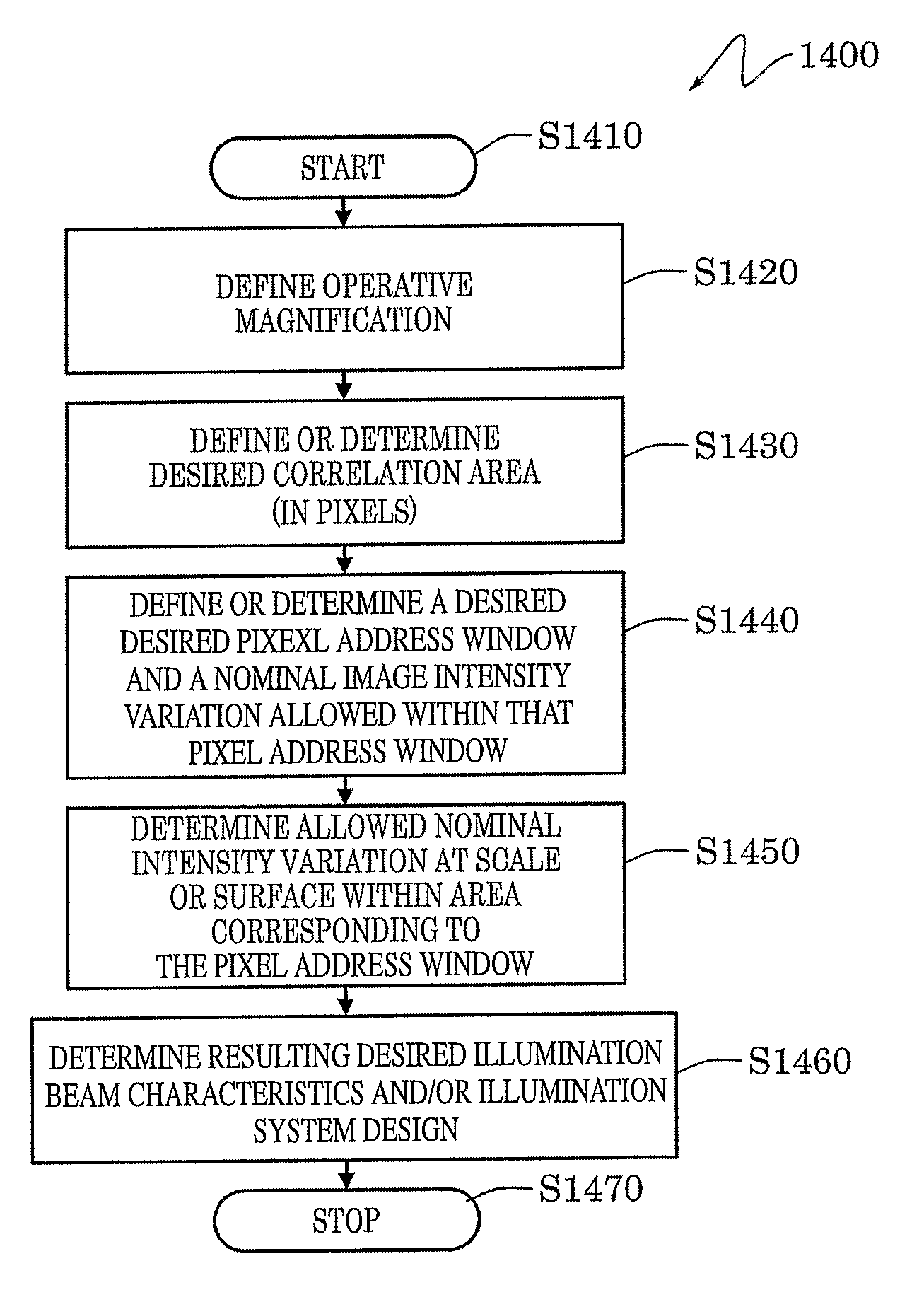
However, the inventors have determined that this obvious and conventional, approach to system design fails to consider several important system problems that occur in the design and operation of a practical product.
For example, this conventional approach may lead to disadvantageous requirements on various assembly tolerances and / or the allowable tolerances when mounting such displacement measuring sensors in the field.
Furthermore, outputting or “acquiring” all pixels of the imaging area of the optical sensor generally decreases the rate at which correlation image acquisition and measurement can be performed, and as a result, generally decreases the displacement speed that is allowable with the associated displacement measuring sensor, thus limiting its utility and / or performance in various applications.

Method used


Image

  • Displacement transducer with selectable detector area
  • Displacement transducer with selectable detector area
  • Displacement transducer with selectable detector area

Examples


Embodiment Construction

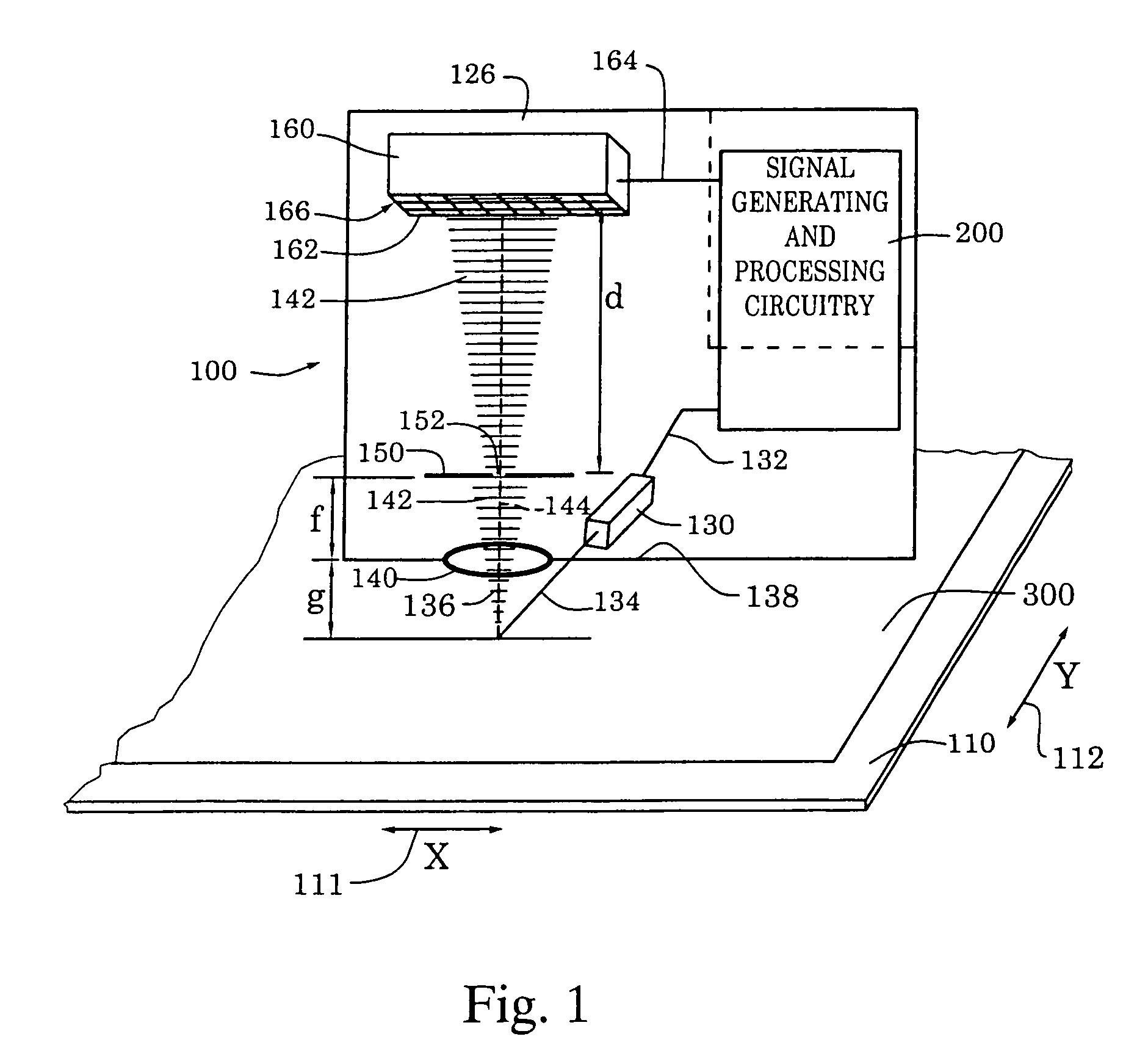
[0036]FIG. 1 is a block diagram of an exemplary optical position transducer 100 usable to generate a position measurement. The optical position transducer 100 includes a readhead 126, signal generating and processing circuitry 200 and a surface 110. The surface 110 may include a scale pattern 300, which may be imaged by the optical position transducer 100 to generate an incremental or absolute position measurement, or the surface may be an optically rough surface from which the optical position transducer 100 may generate a displacement measurement from a speckle pattern arising from the optically rough surface, without the need for a scale pattern. The components of the readhead 126, and their relation to the surface 110 and the scale pattern 300, are shown schematically in a layout that generally corresponds to an exemplary physical configuration, as further described below.

[0037]In particular, the surface 110 is positioned adjacent to an illuminating and receiving end 138 of the ...


PUM


Abstract

A displacement measurement device has a detector area which is larger than the area of the beam spot reflected from the measurement surface. The detector area is made larger than the size of the beam spot on the detector area, in order to accommodate shifts in the location of the beam spot due to changes in the precise locations of the components of the displacement measurement device. The subset of pixels in the detector area having advantageous correlation characteristics, is then selected to perform the correlation calculation, thereby reducing data processing time requirements.

Description

BACKGROUND OF THE INVENTION[0001]1. Field of Invention[0002]This invention is directed to correlation displacement transducers. In particular, this invention is directed to a correlation displacement transducer having a selectable detector area.[0003]2. Description of Related Art[0004]Various known measurement transducers use images acquired by a sensor array, and correlation between images acquired by the sensor array, to determine deformations and / or displacements. For example, one class of such devices is based on acquiring a speckle image generated by illuminating an optically rough surface with a light source. The light source may be a coherent light source, such as a laser-generating light source. Such laser-generating light sources include a laser, laser diode and the like. After the optically rough surface is illuminated by the light source, the light scattered from the optically rough surface is imaged onto an optical sensor. The optical sensor can be a charge-coupled devic...

Claims


Application Information

Patent Timeline
Patent Type & Authority Patents(United States)
IPC IPC(8): G01B11/14G01B11/00G01B11/16G06T7/00
CPCG01B11/002G01B11/16
Inventor EMTMAN, CASEY EDWARDPATZWALD, ANDREW MICHAELJONES, BENJAMIN KEITH
Owner MITUTOYO CORP
Why Eureka
Try Eureka