
Phase extraction in optical processing

a phase extraction and optical processing technology, applied in the field of optical methods and apparatuses, can solve the problems of affecting all real linear transformations, most light detectors are generally sensitive,

Inactive Publication Date: 2009-04-07
LENSLET LABS
View PDF50 Cites 11 Cited by
  • Summary
  • Abstract
  • Description
  • Claims
  • Application Information

AI Technical Summary

Benefits of technology

"The present invention provides a method for determining the sign of data encoded in an output image of a linear optical processor using measurements of intensity of light in the output image. The method involves comparing the intensity of light in the output image with the intensity of light in a reference image generated by the processor. The reference image is generated based on an input image and the phase of the input image. The method can be used to determine the sign of data in the output image by measuring the intensity of light in the combined output image, which is a combination of the output image and the reference image. The technical effect of the invention is to provide a more accurate and reliable method for determining the sign of data in a linear optical processor."

Problems solved by technology

However, a Fourier transform of a data set in general involves complex numbers, even if the data set comprises only real numbers.
While this can be accomplished, most light detectors are generally sensitive only to light intensity and are not responsive to phase.
The problem of distinguishing the sign of numbers represented by an image when only the intensity of light in the image is measured is of course not limited to the case of data optically generated by a cosine transform.
The problem affects all real linear transforms, such as for example the sine and discrete sine transforms and the Hartley transform, when the transforms are executed optically and only their intensities are sensed, if they generate both positive and negative values from a real data set.

Method used


Image

  • Phase extraction in optical processing
  • Phase extraction in optical processing
  • Phase extraction in optical processing

Examples


Embodiment Construction

[0049]In the following discussion an embodiment of the present invention is described in which a real linear transform performed by an optical processor is a cosine transform. The optical processor uses the Fourier transform properties of converging lenses whereby a converging lens transforms an image into its Fourier transform, to generate a cosine transform of an image. The Fourier transform properties of lenses are described in “Introduction to Fourier Optics” by J. W. Goodman, McGraw Hill-Hill Companies, second edition Copyright 1996.

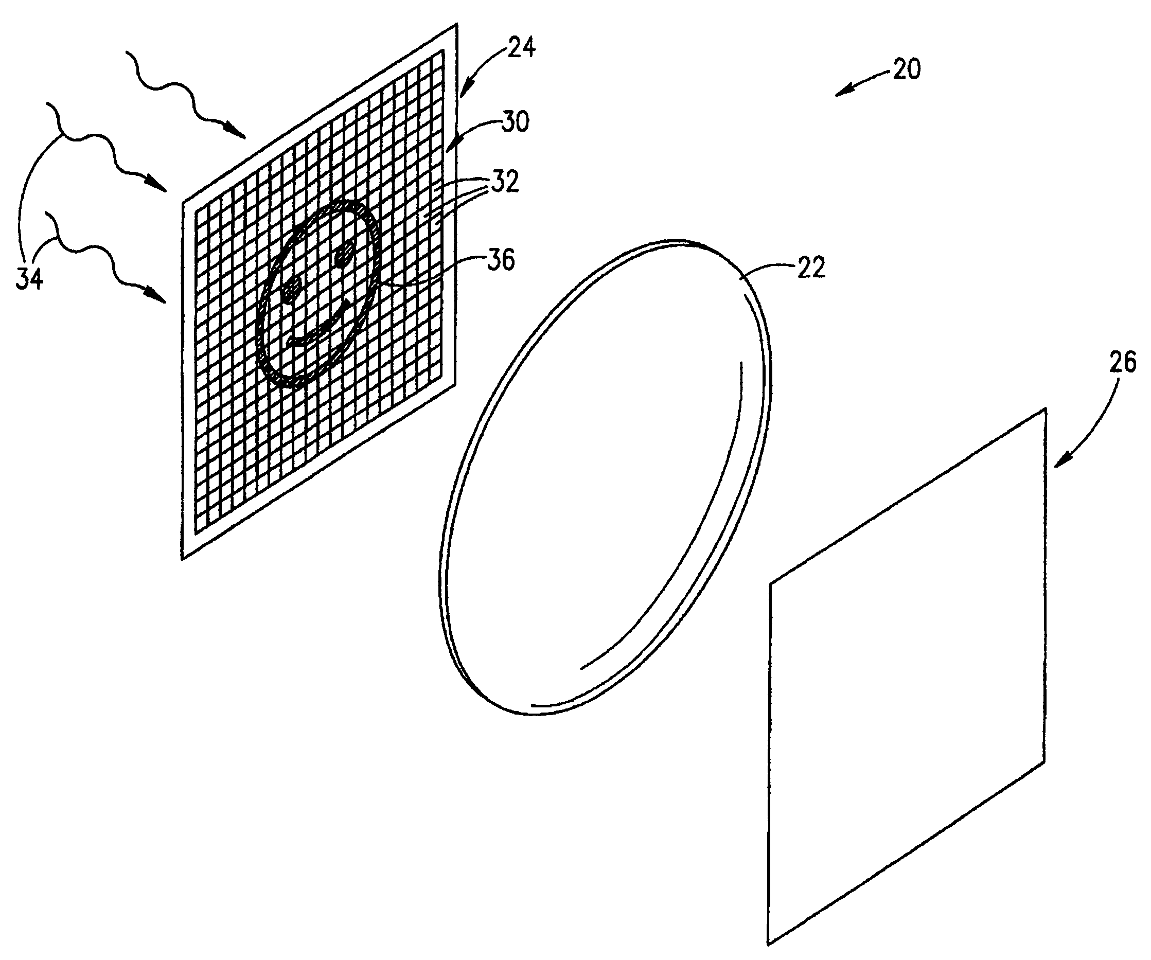
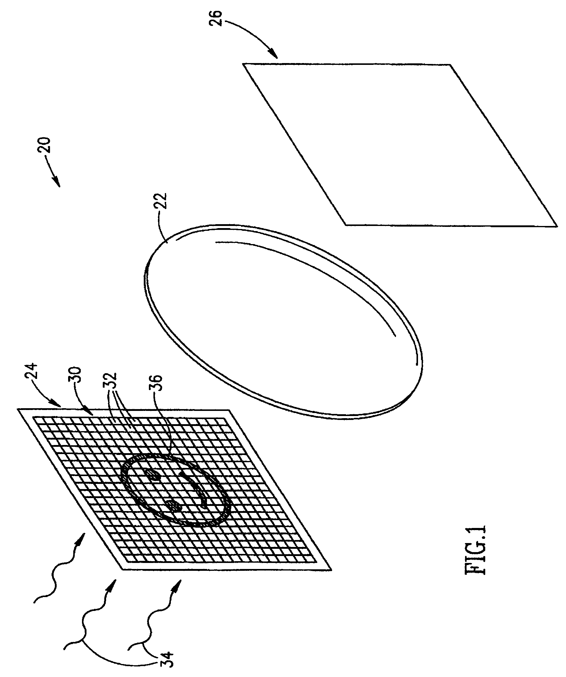
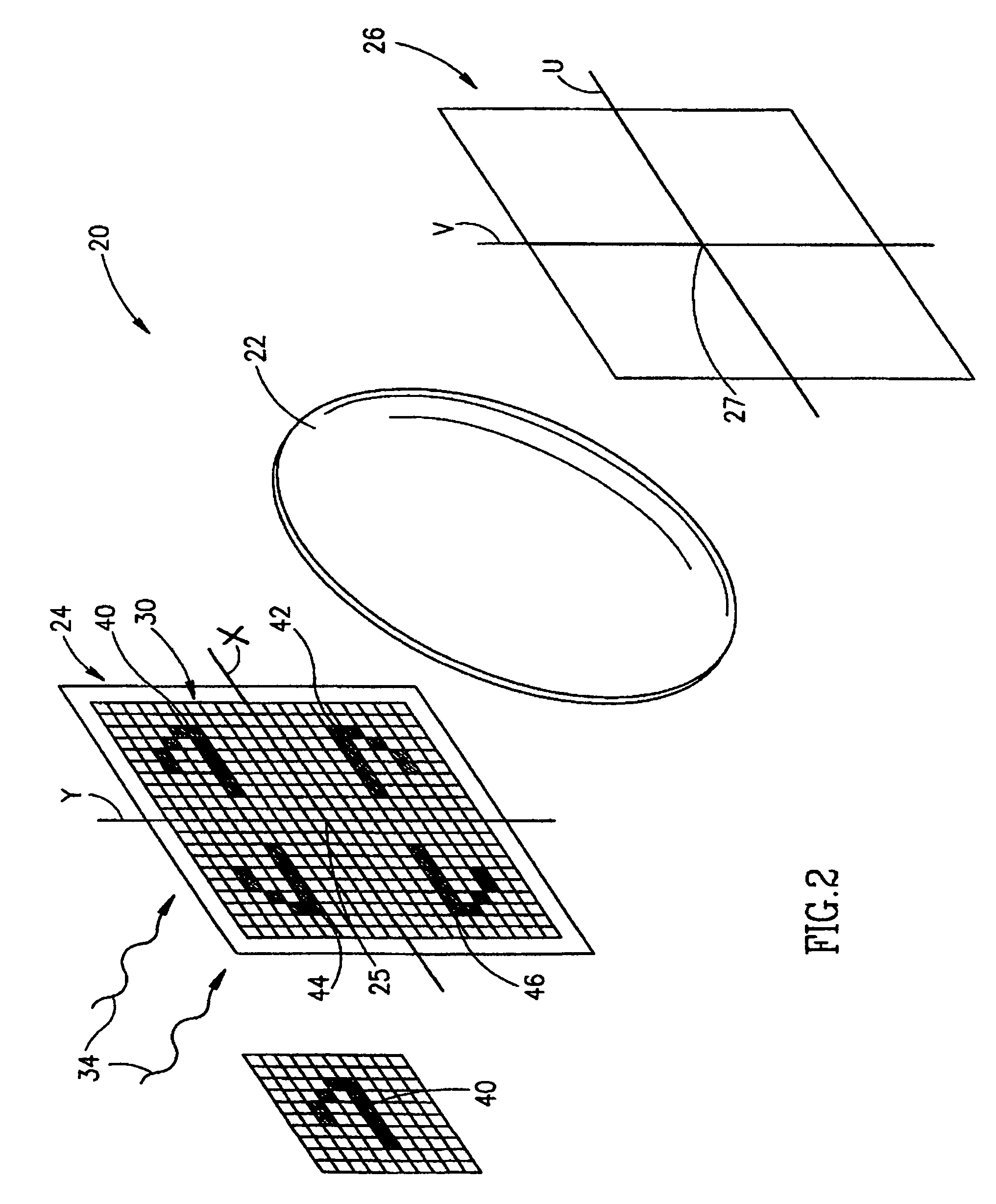
[0050]FIG. 1 schematically shows an optical processor 20 that functions to transform images into their Fourier transforms according to prior art. Optical processor 20 comprises a converging lens 22, an input plane 24 and an output plane 26. Input and output planes 24 and 26 are coincident with focal planes of lens 22. It is well known that lens 22 can be used to generate an image on output plane 26 that is a Fourier transform of an image on input pl...


PUM


Abstract

A method of optical data processing, comprising:providing a first data set to be optically transformed using a transform;combining a reference data set with said first data set to generate coherent light, encoding a combined data set;optically and coherently transforming said light that encodes the combined data set, into coherent light that encodes a transformed combined data set;obtaining a transformed reference data set by determining the effect said optical transform has on light encoding said reference data set; andextracting a second data set that represents a transform of said first data set, from an intensity portion of light encoding said transformed combined data set, using said transformed reference data set to extract a phase of at least one element of said second data set.

Description

RELATED APPLICATIONS[0001]This application is a continuation of U.S. application Ser. No. 09 / 979,182 filed Feb. 25, 2002, now abandoned which is a U.S. national filing of PCT Application No. PCT / IL00 / 00284, filed May 19, 2000. This application is also a continuation in part of PCT application No. PCT / IL99 / 00479, filed Sep. 5, 1999, now U.S. application Ser. No. 09 / 926,547, filed on Mar. 5, 2002 now U.S. Pat. No. 7,194,139, the disclosures of which are incorporated herein by reference.FIELD OF THE INVENTION[0002]The invention relates to optical methods and apparatus for performing computations and in particular to transforming a first data set into a second data set by a linear transformation and determining the phase of data elements in the second data set.BACKGROUND OF THE INVENTION[0003]Optical data processing can often be used to process data more rapidly and efficiently than conventional computational methods. In particular, optical methods can be used to perform linear transfor...

Claims


Application Information

Patent Timeline
Patent Type & Authority Patents(United States)
IPC IPC(8): G06K9/66G06V10/88
CPCG02B27/46G06K9/58G06V10/88
Inventor GOLDENBERG, EFRAIMMENDLOVIC, DAVIDMAROM, EMANUELBERGSTEIN, LEONARDSARIEL, AVIRAM
Owner LENSLET LABS
Learn More