Stent delivery system

Inactive Publication Date: 2009-04-14
BOSTON SCI SCIMED INC
View PDF11 Cites 40 Cited by
  • Summary
  • Abstract
  • Description
  • Claims
  • Application Information

AI Technical Summary

Benefits of technology

[0031]It is yet another object of this invention to provide a method and system for delivery of a stent which reduces the steps and time necessary to deliver a stent to a selected location of a vessel in a patient.
[0032]It is yet still another object of this invention to provi

Problems solved by technology

Second, the delivery system must facilitate the deployment of the stent into contact with the patient's vessel walls once it is located at a selected site.
However, Burton et al. do not provide any indication that the stent has deployed beyond a point at which retraction is no longer possible.
That is, Burton et al. fail to disclose apparatus enabling a surgeon to determine when the axial forces necessary to reduce the expanded portion of the stent have exceeded the frictional bond between the stent and a gripping surface that retains the stent on the catheter.
This also reduces the overall flexibility of the distal end of the stent delivery system.
Maneuvering a distal end of reduced fle

Method used


Image

  • Stent delivery system
  • Stent delivery system
  • Stent delivery system

Examples


Example

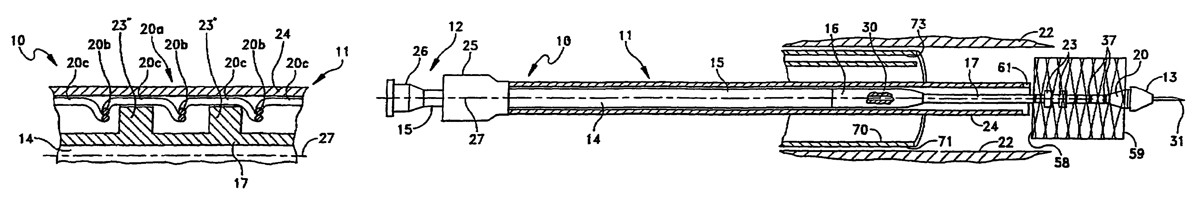
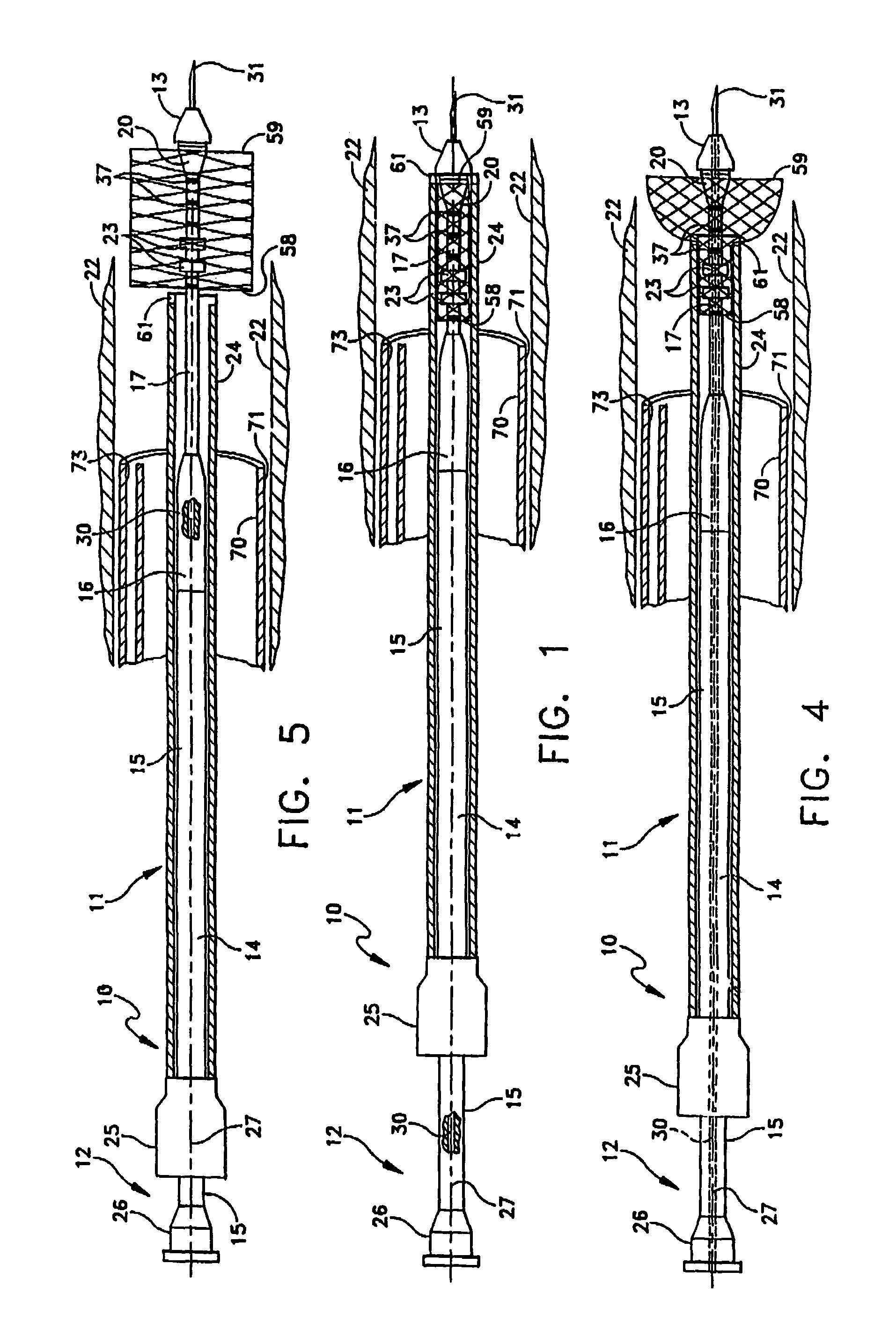
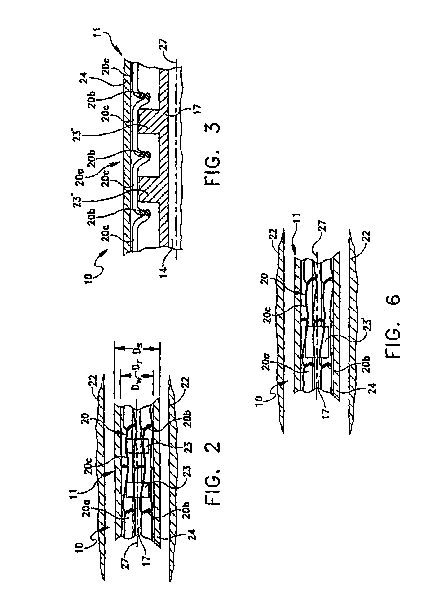
[0044]A stent delivery system 10 according to this invention as depicted in FIG. 1 includes a elongated catheter 11 defined between a proximal handle 12 and a distal end tip 13. An axially extending plastic core 14 supports the distal end tip 13. The core 14 includes a relatively stiff portion 15 extending distally from the handle 12. A flexible thick portion 16 extends distally from the stiff portion 15. A flexible thin distal portion 17 extends between the portion 16 and the distal end tip 13. The flexible thin portion 17 underlies a mesh stent 20 supported in a compacted form within the catheter 11 proximate the distal end tip 13 for deployment from the catheter 11 in an expanded form within a patient's vessel 22.

[0045]First and second closely, but axially spaced rings 23 attach to the thin portion 17 and engage the stent 20. A slippery outer sheath 24, preferably formed of a radially flexible axially stiff material such as Teflon® or other like material, overlies the stent 20 an...


PUM


Abstract

A stent delivery system a catheter has an axially extending inner core and outer sheath. Axially spaced rings extending from a relatively narrow diameter portion of the inner core proximate the distal end thereof. The rings engage proximal portions of a compacted stent disposed within the sheath and over the core and rings. A proximal handle of the system has a first portion that supports the sheath and a second portion that supports the core for relative displacement of the core and the sheath. Retraction of the sheath relative to the core uncovers the stent engaged by the rings which tends to remain stationary relative to the core so that upon partial retraction of the sheath a distal end of the stent expands to its expanded form. Further retraction of the sheath deploys the stent, retracting the core returns the distal portion of the stent into the sheath.

Description

CROSS REFERENCE TO RELATED APPLICATION[0001]This is a continuation application of our U.S. patent application Ser. No. 08 / 526,968 filed Sep. 12, 1995 now U.S. Pat. No. 5,702,418 for a Stent Delivery System.BACKGROUND OF THE INVENTION[0002]1. Field of the Invention[0003]This invention relates to a percutaneous and endoscopic delivery of a stent in a patient's body and more particularly to a stent delivery system including a catheter for the selective deployment of a self-expanding stent.[0004]2. Description of Related Art[0005]Stents are well known endoprostheses. A typical endoprosthetic stent comprises a tubular structure that expands radially from a compact form for transit to an expanded form for implantation. Radial expansion causes the stent to implant into the tissues of a wall of a “vessel” being repaired or bridged to maintain its patency. Such stents may be utilized in body canals, blood vessels, ducts and other body passages, and the term “vessel” is meant to include all s...

Claims


Application Information

Patent Timeline
IPC IPC(8): A61F2/06A61F2/84A61M25/04
CPCA61F2/95A61F2002/9665A61M2025/0008
Inventor RAVENSCROFT, ADRIAN C.
Owner BOSTON SCI SCIMED INC
Why Eureka
Try Eureka