Mobile terminal holder

a mobile terminal and holder technology, applied in the direction of electrical apparatus construction details, substation equipment, electrical generators, etc., can solve the problems of inability to use multimedia functions for as long, large amount of heat generated by batteries, and design consideration of releasing or discharging heat generated by mobile terminals, so as to prevent defective operation of internal components

Inactive Publication Date: 2009-04-14
LG ELECTRONICS INC
View PDF30 Cites 7 Cited by
  • Summary
  • Abstract
  • Description
  • Claims
  • Application Information

AI Technical Summary

Benefits of technology

[0010]Therefore, an object of the present invention is to provide a mounting device for a mobile terminal configured to prevent defective operation of internal components of a mobile terminal due to degraded reliability thereof, and to provide for comfortable use thereof.

Problems solved by technology

However, because the battery capacity of the mobile terminal is generally limited, users often are unable to use the multimedia function for as long as they want.
One drawback to the use of such a mounting device is that a large amount of heat may be generated from the battery when the mobile terminal is used for a long period of time while mounted on the mounting device.
However, because the conventional mounting device is designed only for recharging, rather than for extended use of a mobile terminal while mounted therein, releasing or dissipation of the heat generated from the mobile terminal has not been accounted for in the design.
For this reason, if a mobile terminal is used for a long period of time while mounted on the mounting device, a temperature of the mobile terminal may be increased to undesirable levels.
This can result in defective operation of components within the mobile terminal, and degraded reliability thereof.
Also, when a phone call is received while the mobile terminal is being used on the mounting device, such high temperature heat generated from the mobile terminal may be uncomfortable for the user.

Method used


Image

  • Mobile terminal holder
  • Mobile terminal holder
  • Mobile terminal holder

Examples


Embodiment Construction

[0025]Embodiments of the present invention will be described in detail with reference to the accompanying drawings.

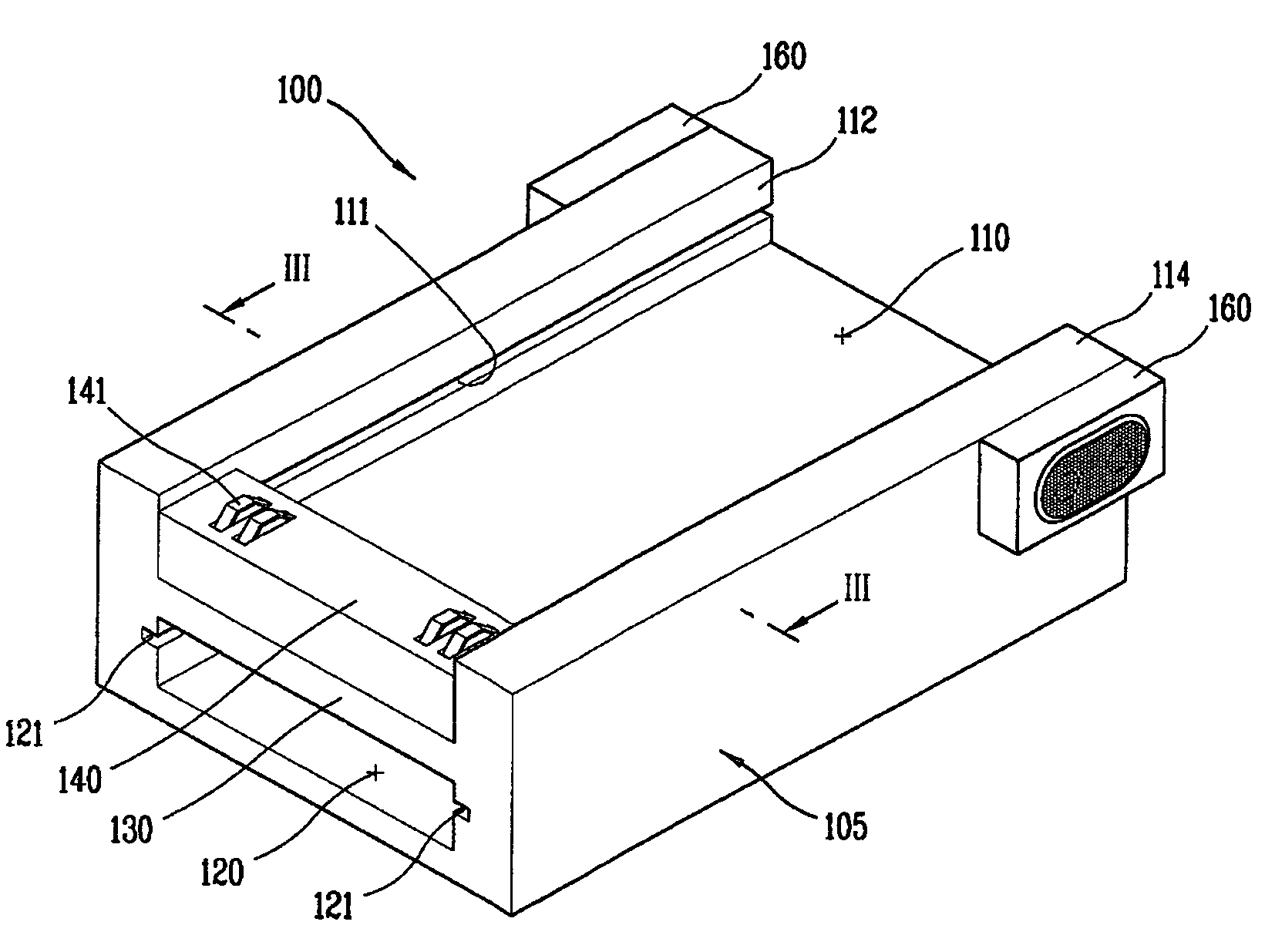
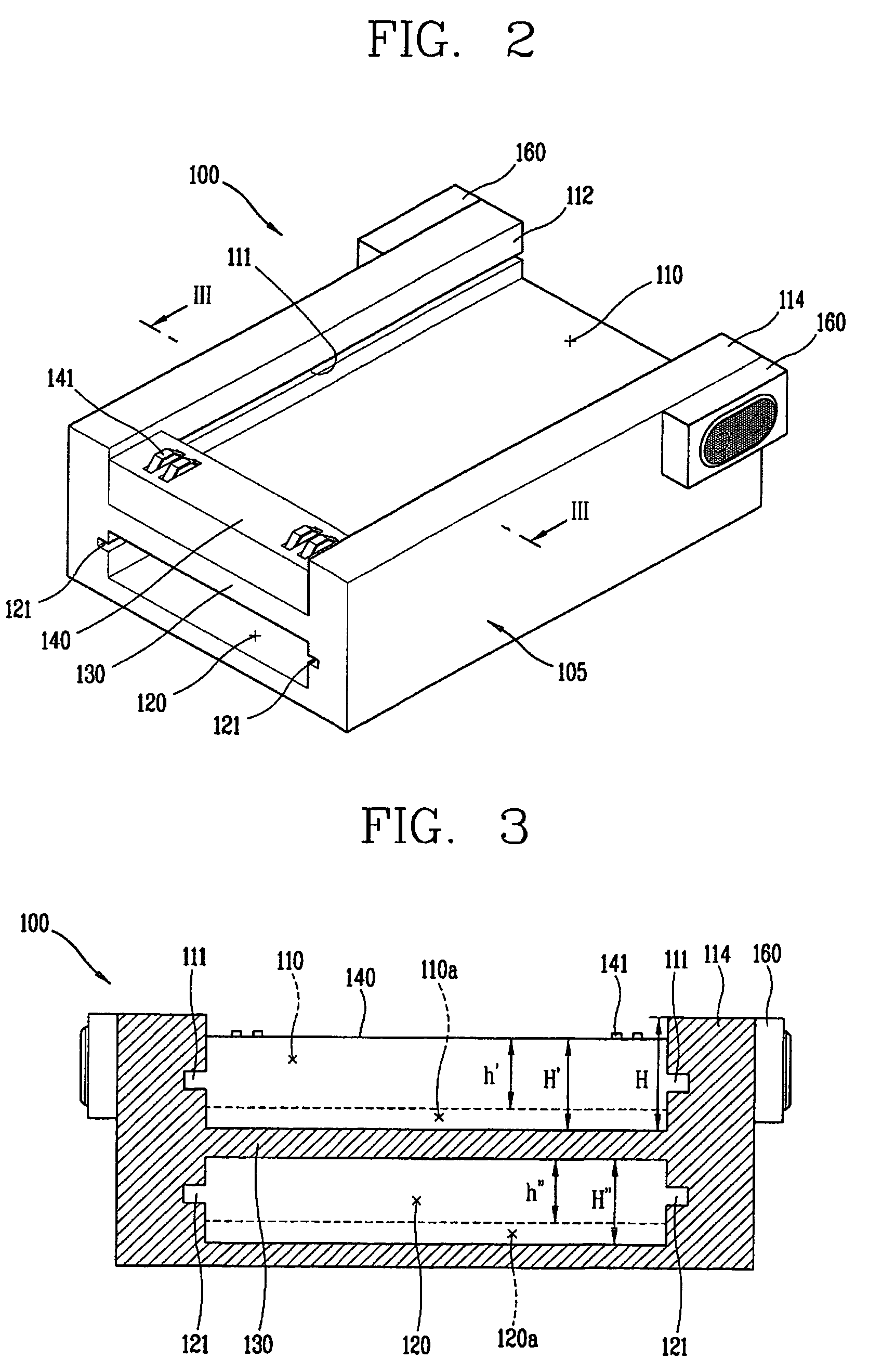
[0026]FIG. 2 is a perspective view of a holder or mounting device for a mobile terminal in accordance with an embodiment of the present invention, and FIG. 3 is a sectional view taken along line III-III of FIG. 2. FIG. 4 is a perspective view of a cooling element or pad used in the mobile terminal holder in accordance with an embodiment of the present invention, and FIG. 5 is a perspective view of a mobile terminal which is mounted in the holder in accordance with an embodiment of the present invention.

[0027]As shown, a holder 100 for a mobile terminal in accordance with an embodiment of the present invention includes a body 105 on which a mobile terminal 200 is mounted, and a cooling pad 150 received in the body 105 for releasing or dissipating the heat generated from the mobile terminal 200 to the outside by heat exchange. It is noted that the mobile terminal can be a...


PUM


Abstract

A mobile terminal holder includes a body configured to receive a mobile terminal mounted thereon, and a receiving portion provided in the body. The receiving portion is configured to receive a cooling element for heat-exchange with a mobile terminal mounted on the body. Even if the mobile terminal is used for a long period of time mounted on the holder, heat generated from the mobile terminal can be effectively dissipated. In this manner, defective operation of the mobile terminal, due to degradation in reliability of components resulting from temperature increase of the mobile terminal, can be prevented.

Description

BACKGROUND OF THE INVENTION[0001]This application claims the benefit of Korean Application No. 10-2004-93649, filed on Nov. 16, 2004, which is hereby incorporated by reference in its entirety.[0002]1. Field of the Invention[0003]The present invention relates to a mounting device for a mobile terminal, and in particular to a holder for a mobile terminal configured to effectively dissipate heat generated by a mobile terminal.[0004]2. Description of the Background Art[0005]FIG. 1 is a perspective view that illustrates a conventional mounting device for a mobile terminal. A conventional mounting device 10 for a mobile terminal includes a mounting groove 11 in which the mobile terminal is mounted. Longitudinal side walls 13 of the mounting groove 11 are formed higher than a lower surface 12 of the mounting groove 11. A charging terminal 14 is provided at a lowermost end of the lower surface 12, and is configured to electrically contact a battery charging terminal of a mobile terminal ins...

Claims


Application Information

Patent Timeline
Patent Type & Authority Patents(United States)
IPC IPC(8): H04M1/00
CPCH02J7/0044H04M1/06
Inventor SON, HYUN-WUNG
Owner LG ELECTRONICS INC
Why Eureka
Try Eureka