Micro coaxial cable connector assembly

a coaxial cable and connector technology, applied in the direction of coupling contact members, coupling device connections, coupling/disconnecting parts, etc., can solve the problems of laborious and expensive sooting process

Inactive Publication Date: 2009-04-21
HON HAI PRECISION IND CO LTD
View PDF3 Cites 23 Cited by
  • Summary
  • Abstract
  • Description
  • Claims
  • Application Information

AI Technical Summary

Benefits of technology

[0003]However, The wires must be securely soldered to a plurality of contacts of the cable connector to transmit signals in a reliable manner. To avoid this problem, in the prior art, the wires are one by one manually soldered to the contacts. Such a soldering process is laborious and expensive.

Problems solved by technology

Such a soldering process is laborious and expensive.

Method used


Image

  • Micro coaxial cable connector assembly
  • Micro coaxial cable connector assembly
  • Micro coaxial cable connector assembly

Examples


Embodiment Construction

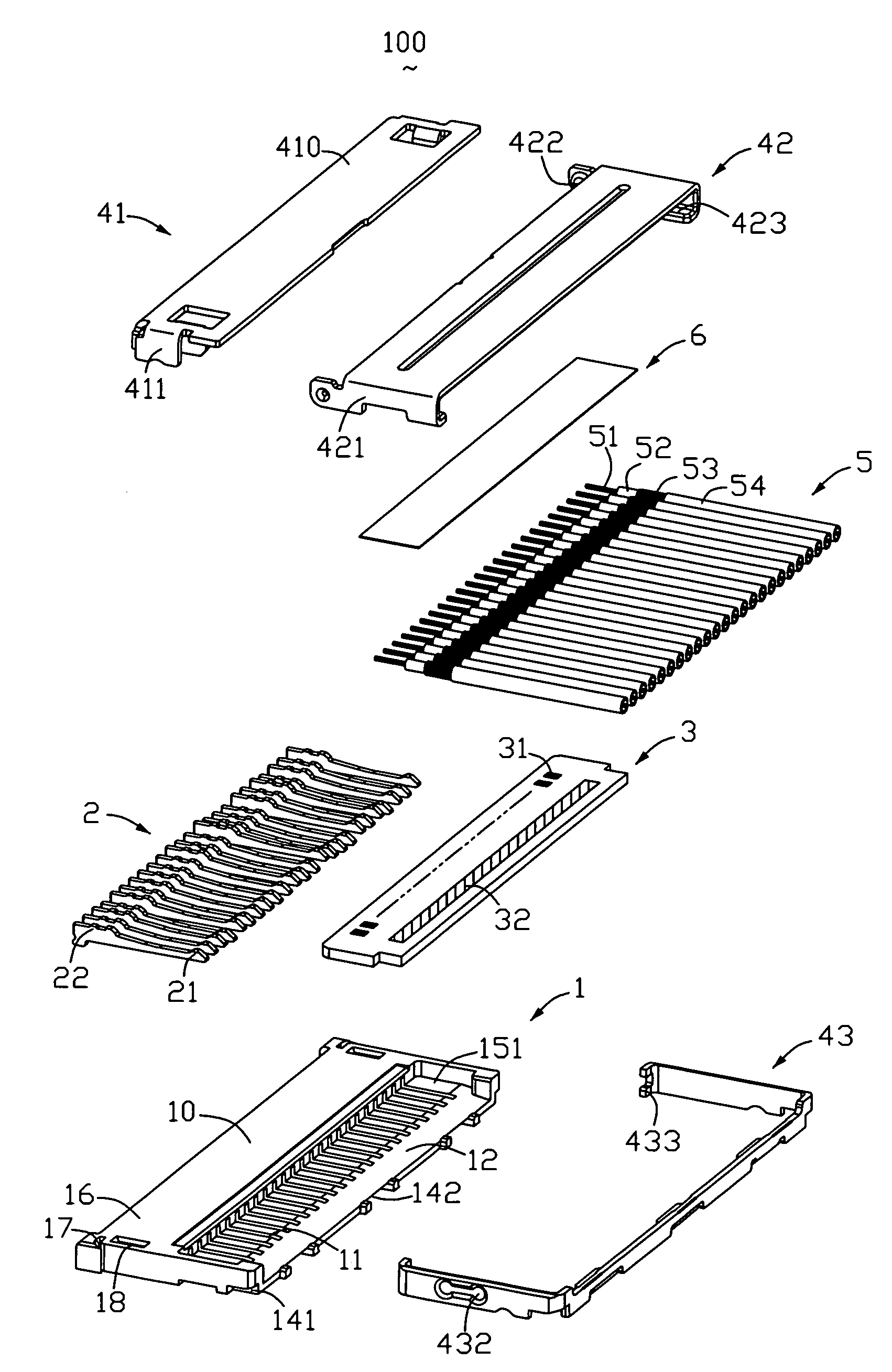
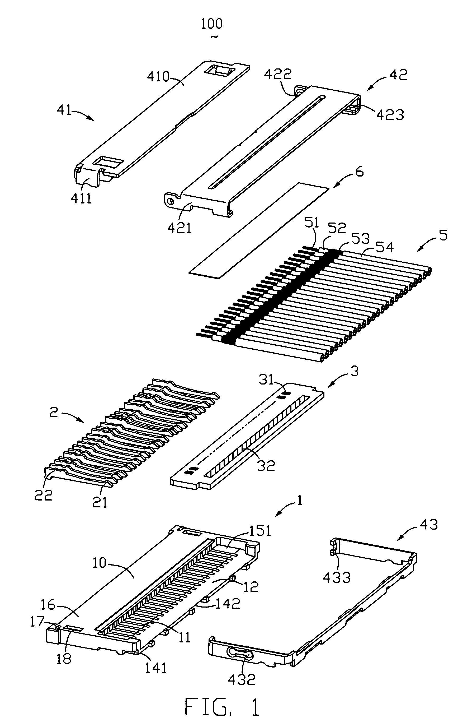
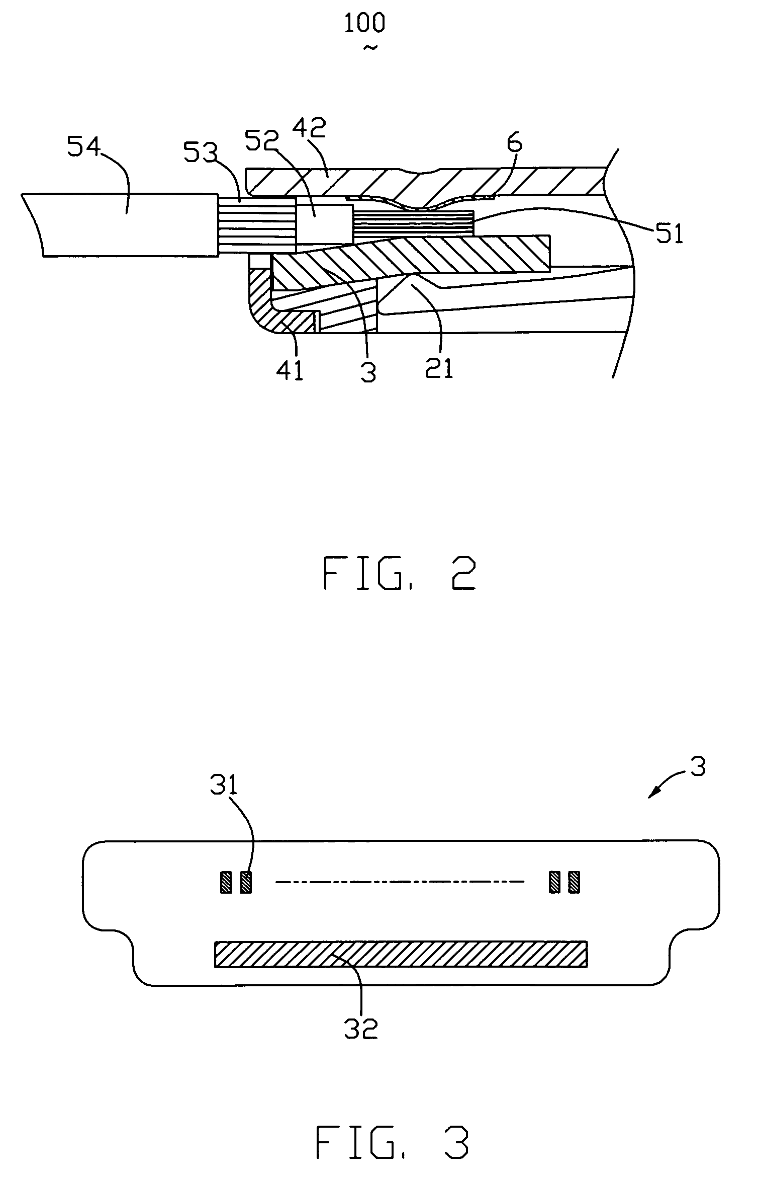
[0011]Referring to FIGS. 1, a low profile micro coaxial cable connector 100 of the present invention comprises an insulative housing 1, a plurality of contact terminals 2, an insulative film 6, and a FPC (FLEXIBLE PRINTED CIRCUITS BOARD) 3 received in the insulative housing 1. A shield 4 made of metal covered onto the insulative housing 1.

[0012]The insulative housing 1 comprises an elongate base portion 10, a tongue portion 12 extending forwardly from the base portion 10, an upper surface 16 at a top of the base portion 10, and a pair of buckling portion 17 formed on lateral ends of the base portion 10. A pair of slots 18 is defined in an upper surface of base portion 10. The base portion 10 and the tongue portion 12 together define a plurality of passageways 11 from the rear end of the base portion 10 to a front end of the tongue portion 12. A receiving space 151 is formed on lateral ends of the insulative housing 1. The bottom of the receiving space 151 defines a pair of recesses ...


PUM


Abstract

An micro coaxial cable connector assembly, comprising: an elongate insulative housing having a base portion, a tongue portion extending from the base portion, and a plurality of passageways defined through the base portion and the tongue portion; a plurality of contacts received in the passageways of the insulative housing; a FPC received in the tongue portion; a plurality of wires soldered on the FPC received in the tongue portion; a conductive grounding shield covered onto the insulating housing and the tongue portion; a insulative film adhibited under the conductive grounding shield so that the assembly of the electrical connector is convenient.

Description

FIELD OF THE INVENTION[0001]The present invention related to an electrical connector, and more particularly, to an electrical connector having slideably mounted actuating device to securely and electrically interconnect a cable assembly thereon when the actuating device is located at a closed position.DESCRIPTIONS OF RELATED ARTS[0002]U.S. Pat. No. 6,685,495 B1 discloses low profiled micro coaxial cable connector, this micro coaxial cable connector comprises an elongate insulative housing, a contact set received in the housing, and a plurality of the wires inserted into the contact set. The insulative housing comprises a base portion, a tongue portion extending from the base portion, and a plurality of passageways defined through the base portion and the tongue portion. The contact set is assembled to a rear end of the housing and comprises an insulative insert and a plurality of contacts, the insulative insert includes a plurality of channels, the contacts are received in the chann...

Claims


Application Information

Patent Timeline
Patent Type & Authority Patents(United States)
IPC IPC(8): H01R13/04
CPCH01R9/037H01R9/038H01R9/0524H01R12/592H01R13/65917H01R13/65918
Inventor WATANABE, TSUNEKI
Owner HON HAI PRECISION IND CO LTD
Why Eureka
Try Eureka