Compression connector for coaxial cable

a technology of compression connector and coaxial cable, which is applied in the direction of coupling device connection, two-part coupling device, electrical apparatus, etc., can solve the problems of prone to installation errors, 50 ohm connectors require labor intensive and crafty installation, and the connectors used in both approaches are relatively expensive. , to achieve the effect of reducing the required insertion length of the prepared cable, preventing both the dislocation of the cable within the connector and the damage of the cabl

Active Publication Date: 2006-04-18
RF IND
View PDF27 Cites 205 Cited by
  • Summary
  • Abstract
  • Description
  • Claims
  • Application Information

AI Technical Summary

Benefits of technology

[0012]The use of a floating, deformable compression ring as described above solves two of the problems associated with installing 50 ohm connectors on smaller diameter coaxial cables. First, the use of a deformable compression ring results not only in the ability to accommodate different cable diameters but reduce the distance between the opening of the connector and the end of the post. This permits reducing the required insertion length of the prepared cable to be relatively short. Additionally, the floating nature of the compression ring makes possible the advantageous configuration of completely trapping the compression ring within the body of the compression connector, thereby ensuring that the compression ring remains in place prior to installation on a cable. The floating ring of the present invention removes element of relative motion between the connector and the cable. The compression wedge of the present invention slides along the outer surface of the compression ring. The compression ring therefore serves to isolate the cable from the moving compression wedge from the cable, thereby preventing both dislocation of the cable within the connector and damage to the cable from the sliding compression wedge.

Problems solved by technology

Present 50 ohm connectors require labor intensive and craft sensitive installation.
The connectors used in both of these approaches are relatively expensive due to the number of precision parts involved.
Furthermore, both of these approaches are prone to installation errors that may not be readily apparent to the installer, e.g., the threaded body sections are not fully tightened together.
The relative motion between the connector component and the cable may result in damage to the cable which in turn may degrade the operational effectiveness and reliability of the deployed cable.

Method used


Image

  • Compression connector for coaxial cable
  • Compression connector for coaxial cable
  • Compression connector for coaxial cable

Examples


Embodiment Construction

[0038]Reference will now be made in detail to the present preferred embodiments of the invention, examples of which are illustrated in the accompanying drawings. Whenever possible, the same reference numerals will be used throughout the drawings to refer to the same or like parts for clarity.

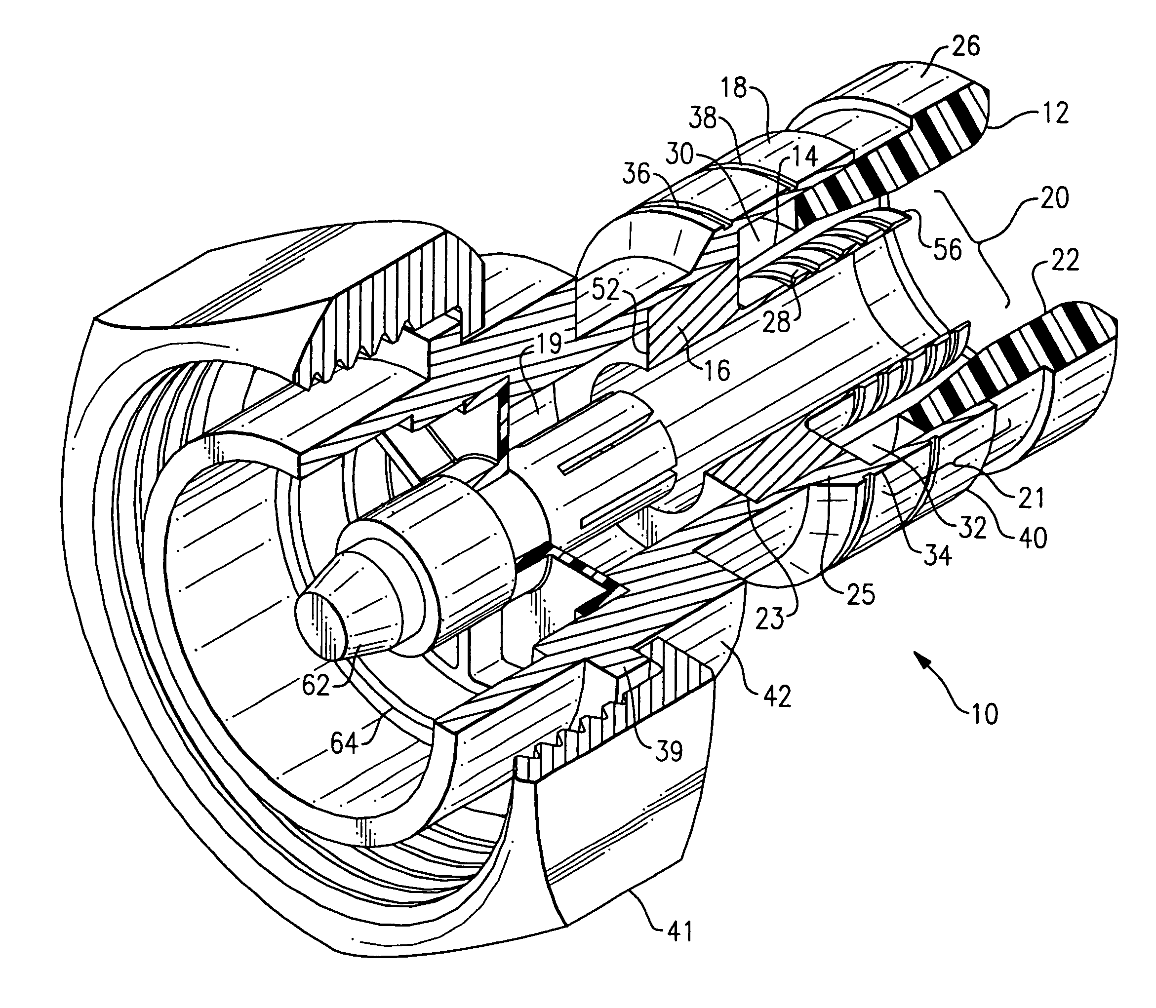
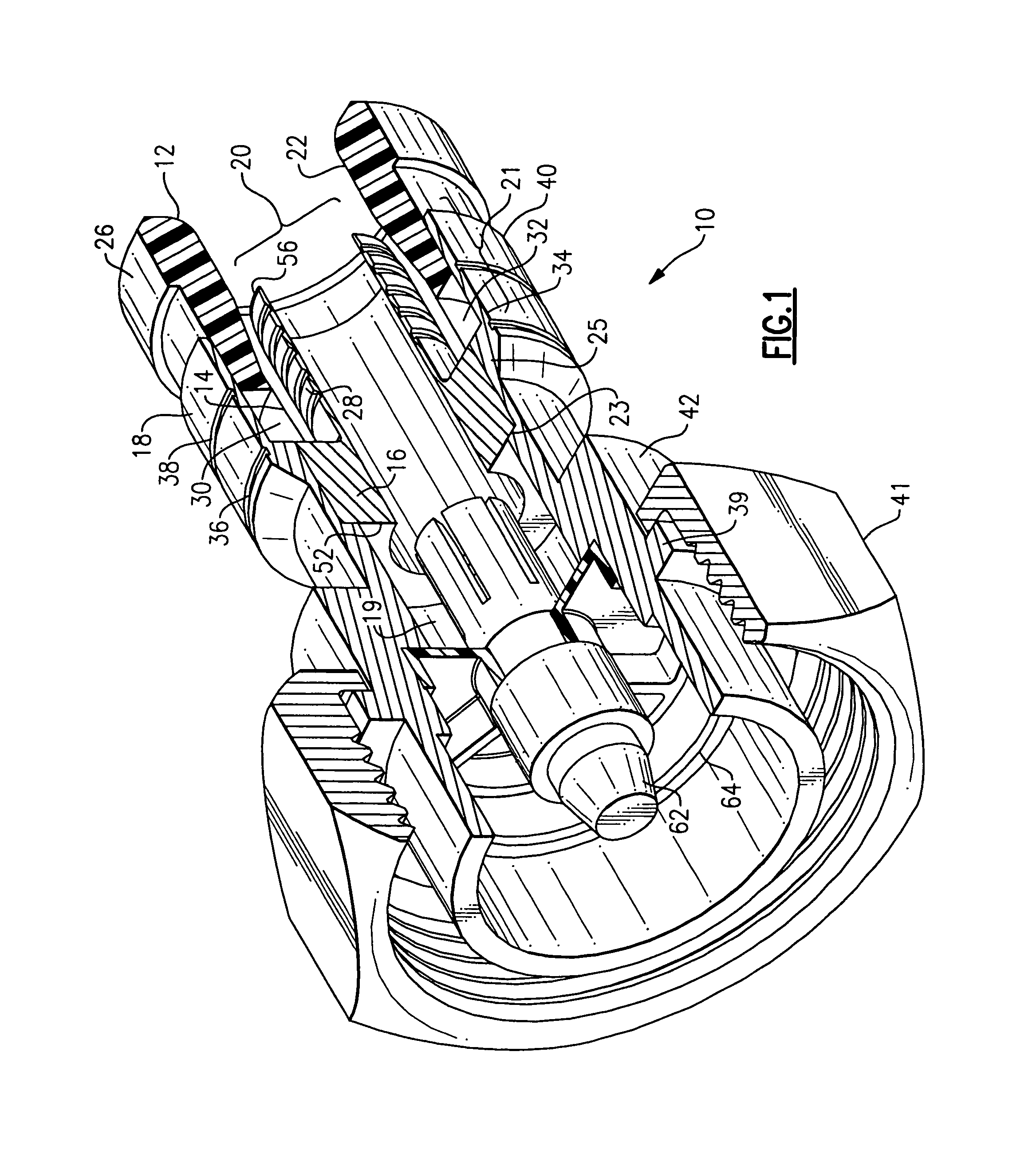
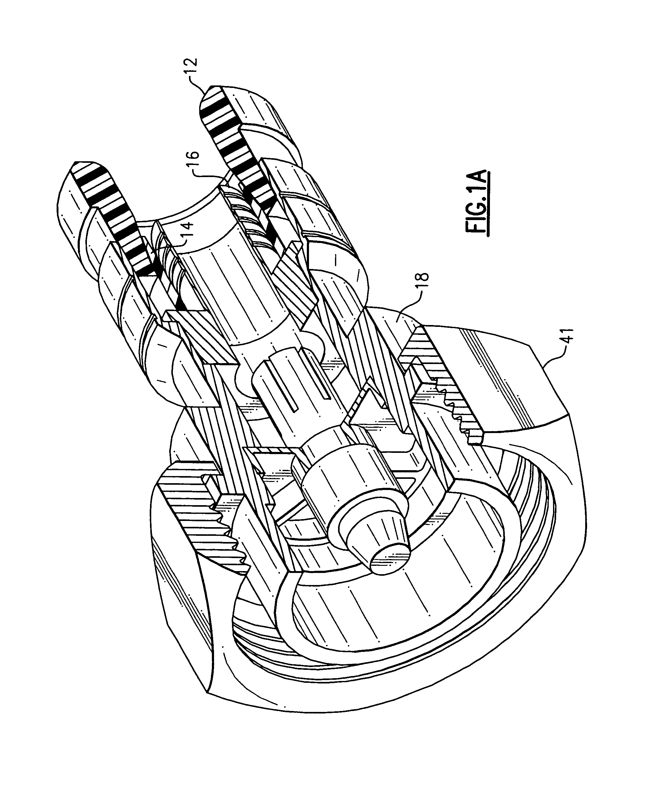
[0039]According to one embodiment, as shown in FIG. 1, the present invention for a compression connector 10 for a coaxial cable. The embodiment of the compression connector 10 shown in FIGS. 1 and 2 is configured as a DIN male connector; further embodiments of the present invention incorporating different connectors are described below. Coaxial cable typically includes a center conductor surrounded by a dielectric layer, which is in turn surrounded by an outer conductor or grounding sheath. The outer conductor may include layers of conductive foils, a braided mesh of conductive wires or a combination of both. The outer conductor or grounding sheath is in turn surrounded by an outer protective ja...


PUM


Abstract

A coaxial cable compression connector includes a connector body having a first end and a second end, and an internal passageway. The compression connector further includes a tubular post having a first end configured for engagement with the conductive grounding sheath of the coaxial cable and a second end configured for engagement with the internal passageway of the body. The connector further includes a compression member. The first end of the compression member includes an outer surface and a tapered inner surface, the outer surface is configured for engagement with a portion of the internal passageway at the first end of the body. The connector further includes a ring member which is configured for engagement with the tapered inner surface of the compression member.

Description

FIELD OF THE INVENTION[0001]This invention relates to terminals for coaxial cables and more particularly to compression terminals for coaxial cables.BACKGROUND OF THE INVENTION[0002]The deployment of 50 ohm coaxial cable, such as, for example 200, 400 and 500 sizes of cable, for video and data transfer is increasing. Present 50 ohm connectors require labor intensive and craft sensitive installation. In one proposed approach the 50 ohm connector is supplied as a kit and is assembled onto a coaxial cable in stages. The assembly must occur in a set order and requires soldering for proper assembly. Another proposed approach uses multiple threaded body sections and requires the use of multiple wrenches to draw the separate body sections together thereby exerting a clamping force on to the cable. The connectors used in both of these approaches are relatively expensive due to the number of precision parts involved. Furthermore, both of these approaches are prone to installation errors that...

Claims


Application Information

Patent Timeline
Patent Type & Authority Patents(United States)
IPC IPC(8): H01R9/05
CPCH01R9/0524H01R24/40H01R13/622H01R2103/00H01R13/623H01R9/05
Inventor MONTENA, NOAH
Owner RF IND
Why Eureka
Try Eureka