Thumb release mounting apparatus

a cradle and cradle technology, applied in the direction of machine supports, instruments, portable computers, etc., can solve the problems of current mounting, ineffective releasably cradling, inability to provide universal cradling, etc., to achieve convenient and secure cradling, easy removal of the device, and quick drawing

Inactive Publication Date: 2009-04-28
NAT PRODS
View PDF43 Cites 26 Cited by
  • Summary
  • Abstract
  • Description
  • Claims
  • Application Information

AI Technical Summary

Benefits of technology

[0007]The present invention is a universal cradle apparatus that overcomes known limitations of prior art apparatus for securing an array of different hand-held or personal devices by providing a spring-return clamping mechanism that permits such hand-held or personal devices to be easily and securely cradled, while permitting quick drawing and easy removal of the device.

Problems solved by technology

However, current mounting platforms may be inefficient for effectively securely releasably cradling larger and irregularly shaped devices.
Additionally, current mounting platforms are generally application specific and fail to provide truly universal cradling.

Method used


Image

  • Thumb release mounting apparatus
  • Thumb release mounting apparatus
  • Thumb release mounting apparatus

Examples


Embodiment Construction

[0027]In the Figures, like numerals indicate like elements.

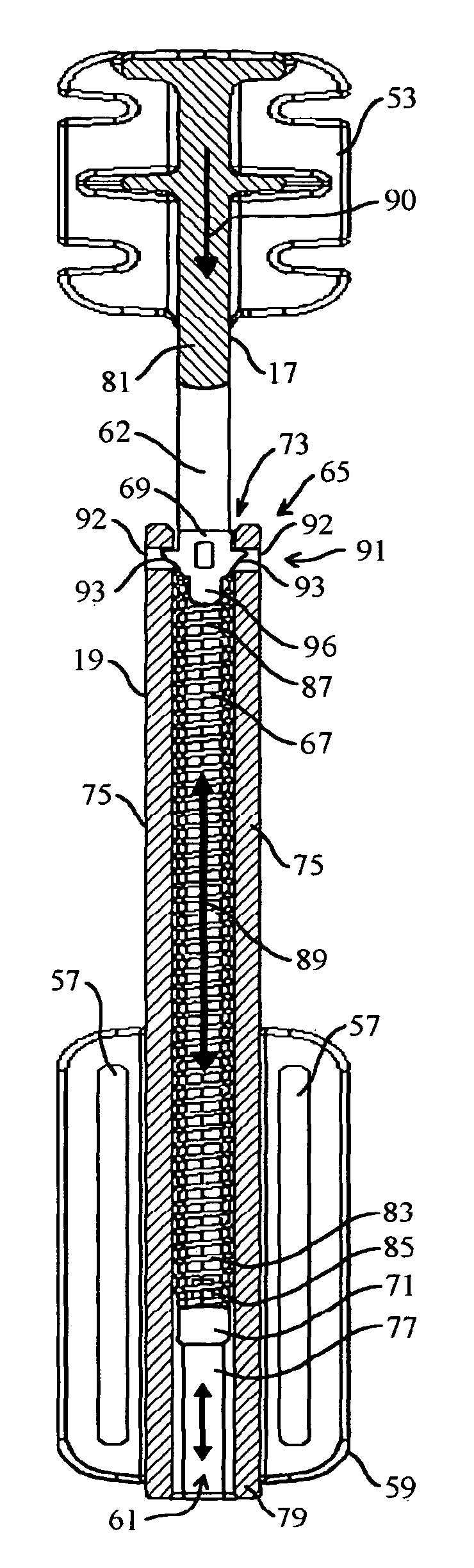
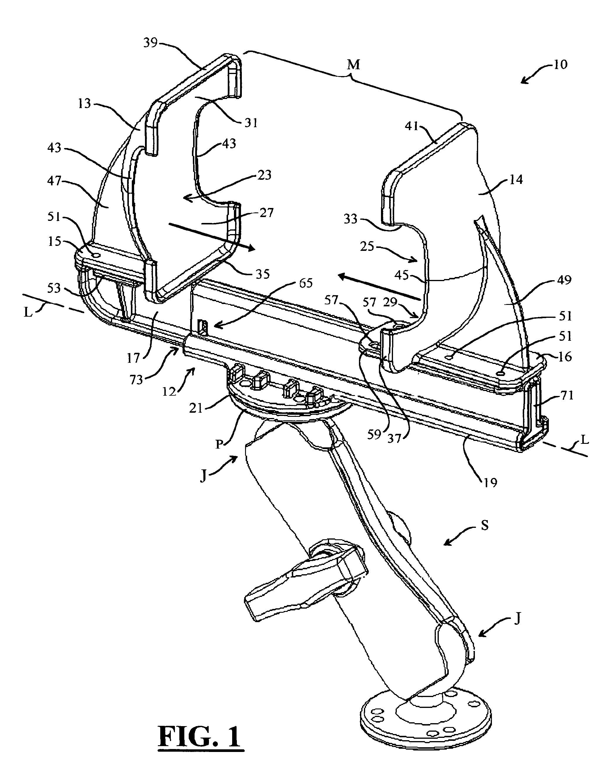
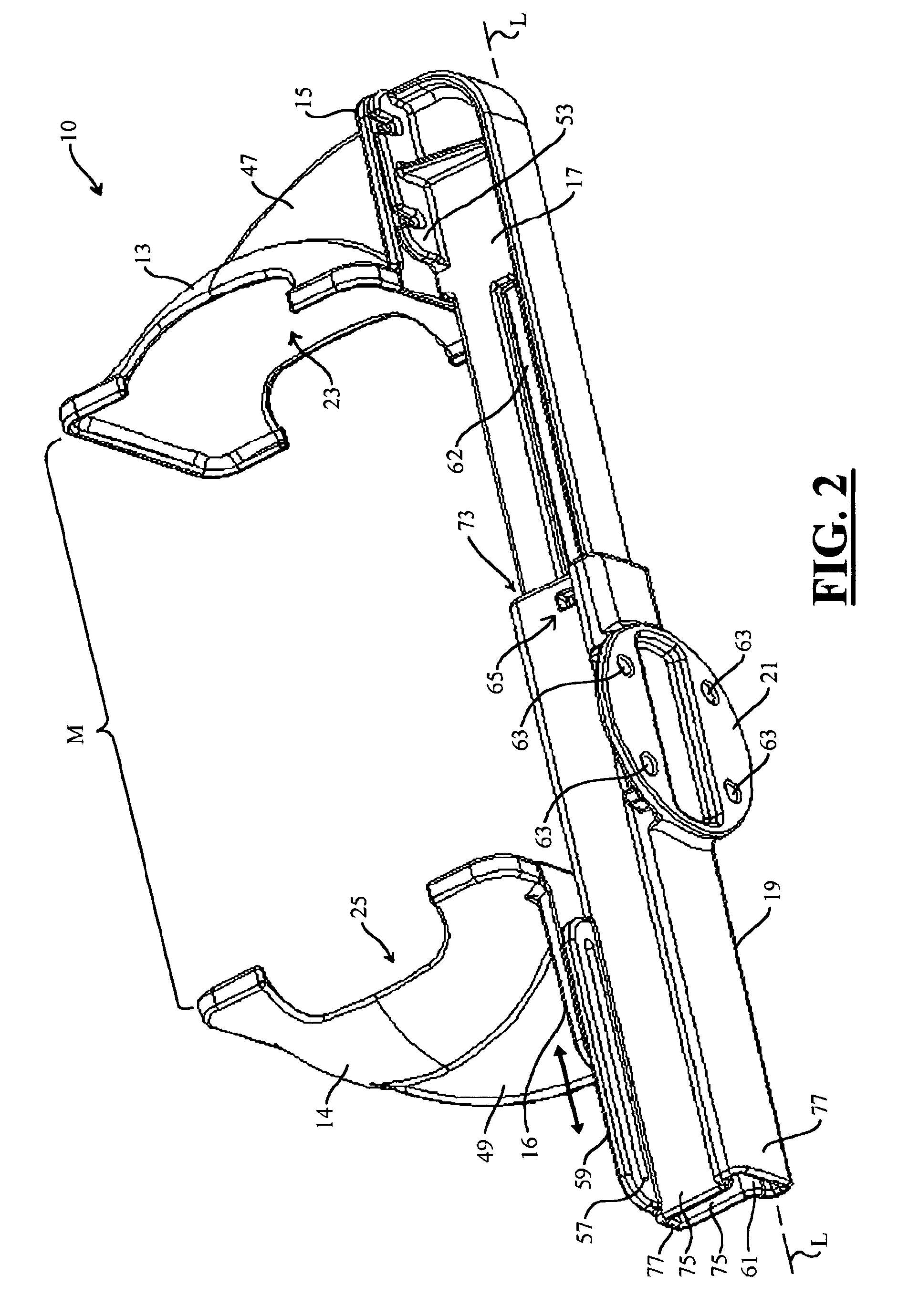
[0028]The universal cradle apparatus of the present invention is embodied by example and without limitation as a pair of substantially rigid jaw structures each configured with a flange structure having a substantially planar mounting surface adapted for being secured to respective cooperating male and female portions of a spring-return clamping mechanism formed of telescoping male linear drive shaft and mating female linear drive channel. The two jaw structures are each configured with a shallow cup-shaped clamping surface that is projected above the respective flange structure. The jaw structures are mounted on the respective drive shaft and drive channel each having its respective cup-shaped interior clamping surface facing toward the clamping surface of the other jaw. A spring is coupled for biasing the male drive shaft into the mating female drive channel of the clamping mechanism, thereby driving the two jaw structures...


PUM


Abstract

A universal cradle apparatus having a pair of substantially rigid jaw structures each configured with a flange structure having a substantially planar mounting surface adapted for being secured to respective cooperating male and female portions of a spring-return clamping mechanism formed of telescoping male linear drive shaft and mating female linear drive channel. One of the two jaw structures is configured with an inclined interior clamping surface that is projected above the respective flange structure and in resiliently flexible relationship therewith. The jaw structures are mounted on the respective drive shaft and drive channel each having its respective interior clamping surface facing toward the clamping surface of the other jaw. A spring is coupled for biasing the male drive shaft into the mating female drive channel of the clamping mechanism, thereby driving the two jaw structures together along a linear drive axis of the clamping mechanism.

Description

RELATED APPLICATIONS[0001]The present application is Continuation-In-Part and claims benefit of co-pending U.S. patent application Ser. No. 11 / 243,846 filed in the name of the inventor of the present application on Oct. 5, 2005, the complete disclosure of which is incorporated herein by reference, which is Continuation-In-Part and claims benefit of co-pending U.S. patent application Ser. No. 11 / 191,549 filed in the name of the inventor of the present application on Jul. 28, 2005, the complete disclosure of which is incorporated herein by reference, and both co-pending U.S. patent application Ser. No. 10 / 636,058 filed in the name of the inventor of the present application on Aug. 7, 2003, and co-pending U.S. patent application Ser. No. 11 / 136,797 filed in the name of the inventor of the present application on May 24, 2005, the complete disclosures of which are both also incorporated herein by reference.[0002]The present application is related to U.S. patent application Ser. No. 11 / 34...

Claims


Application Information

Patent Timeline
Patent Type & Authority Patents(United States)
IPC IPC(8): A44B21/00A47F5/00A44B99/00
CPCB60R11/0241B60R11/0252F16M11/02F16M11/04F16M11/043F16M11/14F16M11/2078F16M13/02G06F1/163G06F1/1632A45F5/00A45C2011/002Y10T24/44573A45F5/02A45F2200/0516B60R2011/0059B60R2011/0071B60R2011/0078F16M2200/022Y10T24/44581Y10T24/44615F16M11/041
Inventor CARNEVALI, JEFFREY D.
Owner NAT PRODS
Why Eureka
Try Eureka