Seating unit with adjustable components

a technology of adjustable components and seating units, which is applied in the field of seating units, can solve the problems of increasing aesthetics, adding components, and cost, and reducing the aesthetics of office chairs, and increasing the difficulty of backs, armrests, and seats

Active Publication Date: 2009-05-05
STEELCASE INC
View PDF78 Cites 80 Cited by
  • Summary
  • Abstract
  • Description
  • Claims
  • Application Information

AI Technical Summary

Benefits of technology

[0007]In one aspect of the present invention, a seating unit includes a base with a laterally-extending tubular support, and an armrest having a tubular end telescopingly engaging the tubular support, with the tubular end having a first sidewall adjacent a similarly-shaped sidewall of the tubular support. A clamp extends through the first sidewall and through the similarly-shaped sidewall and is configured to press the adjacent sidewalls together without crushing other walls of the tubular support and tubular end. By this arrangement, the remaining walls of the tubular support and the tubular end are not stressed in a way that will deform them even when the clamp is clampingly pressing the adjacent sidewalls together.
[0009]In yet another aspect of the present invention, a method of assembly comprising steps of providing a laterally-extending tubular support, providing an armrest having a tubular end, and telescopingly engaging the tubular end into the tubular support, with the tubular end having a first sidewall adjacent a similarly-shaped sidewall of the tubular support. The method further includes providing a clamp having a fastener and a clamp handle, passing the fastener completely through top walls of the tubular support and the tubular end, and extending the fastener through the first sidewall and through the similarly-shaped sidewall, and attaching the clamp handle to an end of the fastener. The method further includes operating the clamp to press the adjacent sidewalls together without crushing other walls of the tubular support and the tubular end, such that remaining walls of the tubular support and the tubular end are not stressed in a way that will deform them even when the clamp is clampingly pressing the adjacent sidewalls together.
[0011]In still another aspect of the present invention, a seat component is provided for a seating unit. The seat component has a shell with a top surface and a bottom surface, and has front, side and rear edges. The top surface and front edge are configured to support a seated user with the front edge being curved forwardly and downwardly and adapted to comfortably support a seated user's legs hanging over the front edge. The side edges of the shell extend from ends of the front edge and each define a downwardly-facing concavity. An upholstery component includes a perimeter and an edge-mounted drawstring extending at least partially around the perimeter. The upholstery component covers the top surface with perimeter edge portions extending around the front, side and rear edges and extending onto the bottom surface in a manner placing the edge-mounted drawstring under the shell and across the concavities of the sides. The drawstring is tensioned and holds the upholstery on the shell. The shell includes outwardly-extending fingers that retain the drawstring against the bottom surface of the shell even in areas of the concavities to improve appearance and assemble-ability, such that the drawstring does not extend linearly across the concavities.

Problems solved by technology

A dilemma is that adjustable features add components, durability issues, and cost.
Armrests, backs, and seats of office chairs offer particularly difficult challenges, since they are in high visibility locations and require styling elegance.
Unfortunately, features intended to increase aesthetics can also add to the cost.
However, the curved front edge forms a concavity under the seat support which requires special treatment in order to pull upholstery tight against the concavity and not let the upholstery merely bridge in a linear fashion across the area of the concavity.

Method used


Image

  • Seating unit with adjustable components
  • Seating unit with adjustable components
  • Seating unit with adjustable components

Examples


Embodiment Construction

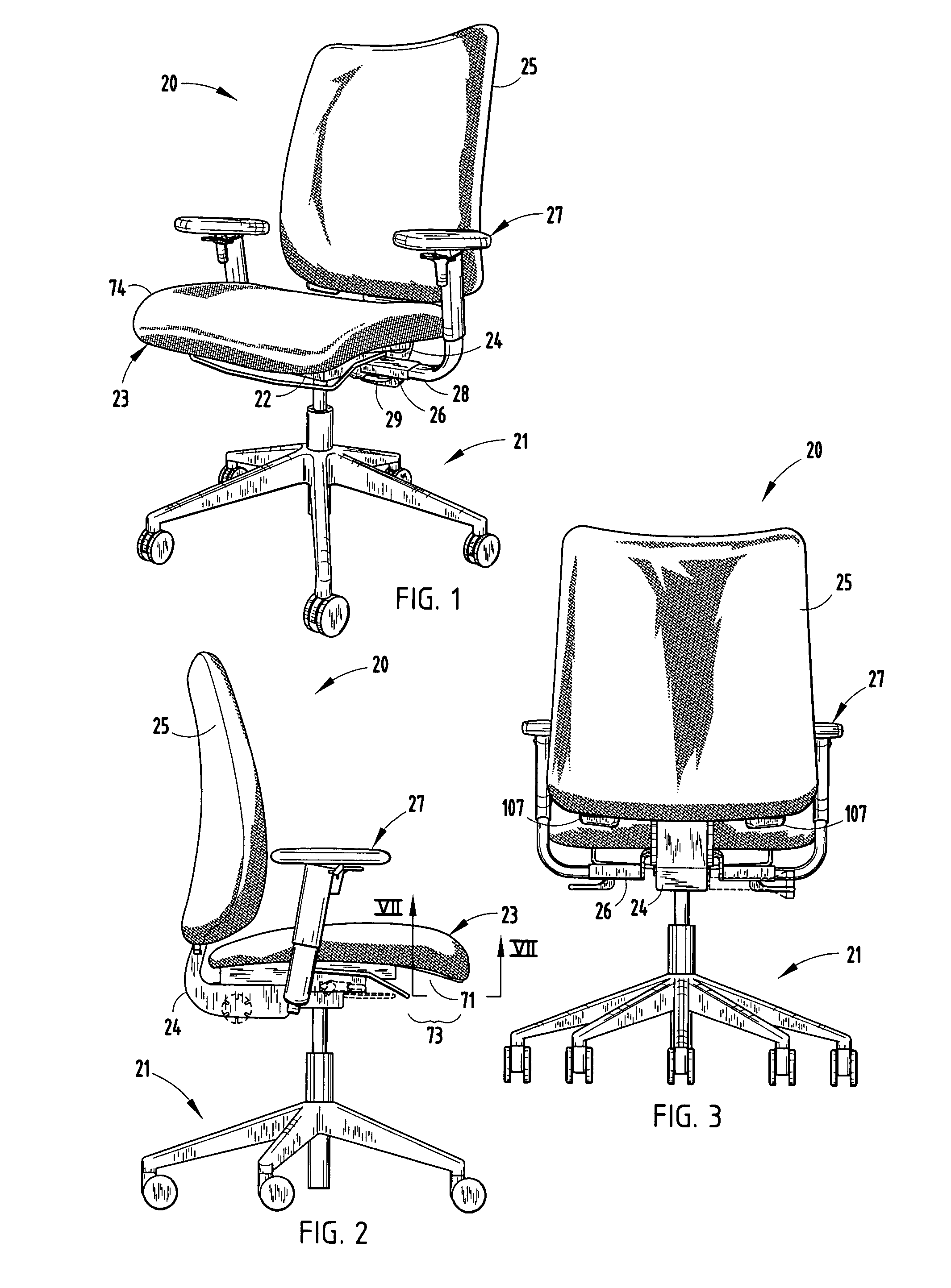
[0022]For purposes of description herein, the terms “upper,”“lower,”“right,”“left,”“rear,”“front,”“vertical,”“horizontal,” and derivatives thereof shall relate to the invention as oriented in FIG. 1. However, it is to be understood that the invention may assume various alternative orientations and step sequences, except where expressly specified to the contrary. It is also to be understood that the specific devices and processes illustrated in the attached drawings and described in the following specification are simply exemplary embodiments of the inventive concepts defined in the appended claims. Hence, specific dimensions and other physical characteristics relating to the embodiments disclosed herein are not to be considered as limiting, unless the claims expressly state otherwise.

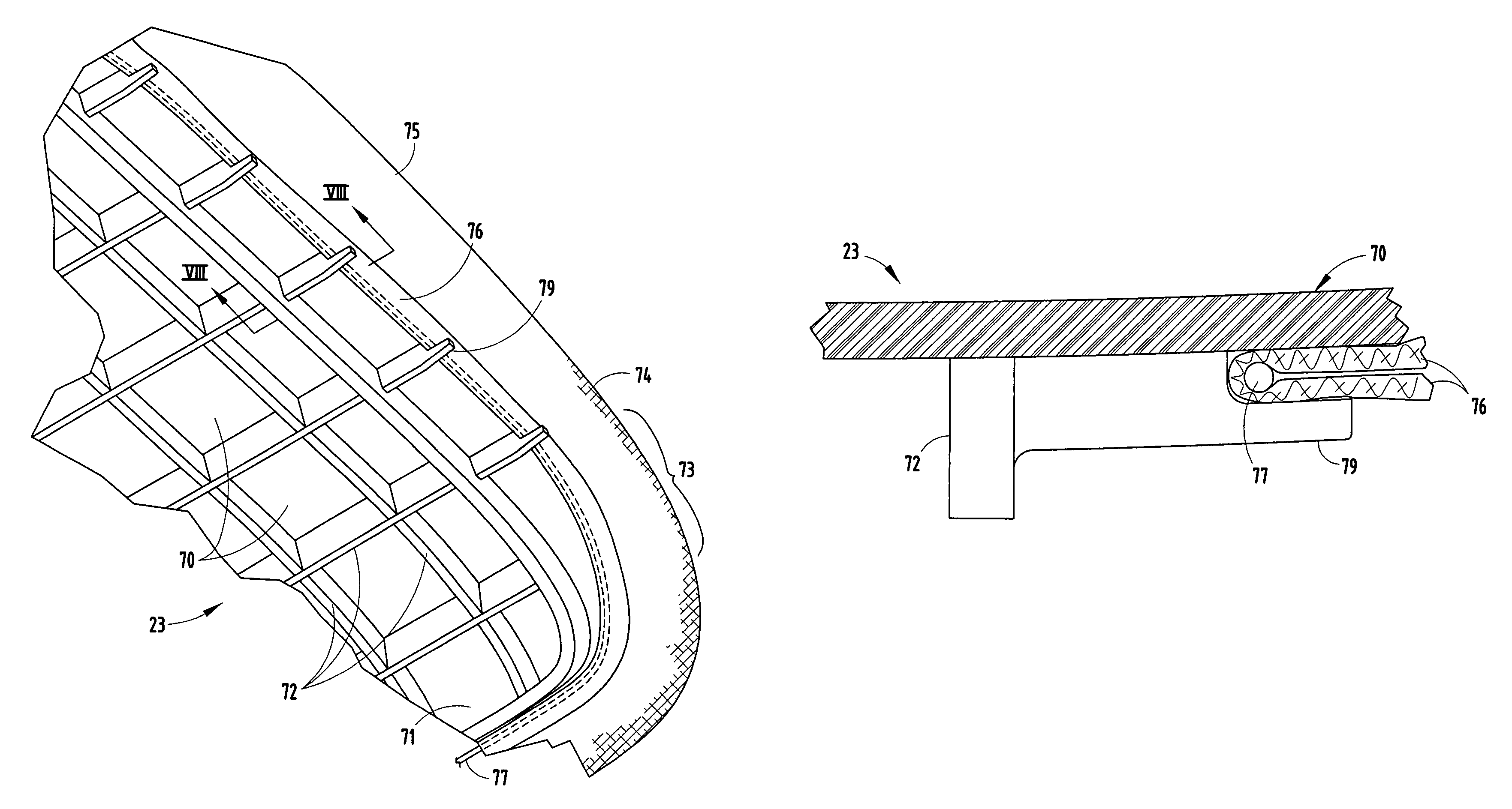
[0023]A synchrotilt seating unit 20 (FIGS. 1-3) includes a base 21 with a control 22, a seat 23 operably supported on the control 22, and a reclinable back 25 supported by an upright 24 extending from a...


PUM


Abstract

An armrest structure includes a tubular support, and an armrest having a tubular end telescopingly engaging the tubular support. A support plate engages bottom walls of the tubular support and the tubular end in a laminar arrangement. A clamping bolt slides through a top hole and into aligned holes in the laminar arrangement, with its head abutting the aligned holes. A clamping handle on a bottom of the bolt is rotatable between a clamping position tensioning the bolt to secure the arrangement, and a release position de-tensioning the bolt. By this arrangement, remaining walls of the tubular support and the tubular end are not deformed even when the clamp is clampingly pressing the adjacent sidewall sections together. An adjustable back with actuator handles at a lower edge of the back, and a seat assembly with fingers that retain an upholstery cover tight against concave areas are also shown.

Description

CROSS-REFERENCE TO RELATED APPLICATION[0001]This application claims the benefit of U.S. Provisional Patent Application No. 60 / 776,983, filed Feb. 27, 2006, the entire contents of which are incorporated herein by reference.[0002]This application is also related to U.S. patent application No. 11 / 711,341, entitled “SEATING UNIT WITH ADJUSTABLE COMPONENTS,” filed on Feb. 27, 2007, and U.S. patent application No. 11 / 711,349, entitled “SEATING UNIT WITH ADJUSTABLE COMPONENTS,” filed on Feb. 27, 2007, the entire contents of each of which are incorporated herein by reference.BACKGROUND OF THE INVENTION[0003]The present invention relates to a seating unit with laterally adjustable armrests and vertically adjustable back, each configured to facilitate assembly and for convenient adjustment, but with hidden components to enhance aesthetics. The present invention also relates to a seat construction with underseat structure that facilitates assembly while maintaining a sleek, low-profile appeara...

Claims


Application Information

Patent Timeline
Patent Type & Authority Patents(United States)
IPC IPC(8): A47C31/02A47C31/11
CPCA47C1/03A47C7/402A47C1/0307
Inventor EBERLEIN, DAVID C.MARTIN, KIRT D.HOUDA, JAMES D.DEKKER, DAVID J.
Owner STEELCASE INC
Why Eureka
Try Eureka