Power supply cover box

a power supply and cover box technology, applied in the direction of flexible lead accommodation, electrical apparatus casing/cabinet/drawer, coupling device connection, etc., can solve the problems of shock and electrical fire hazards to people, large size, and relatively time-consuming operation, so as to reduce the clutter of excessive cords, eliminate excessive cords, and convenient cord storage

Inactive Publication Date: 2009-05-05
WU HSINHAN +1
View PDF11 Cites 66 Cited by
  • Summary
  • Abstract
  • Description
  • Claims
  • Application Information

AI Technical Summary

Benefits of technology

[0020]One advantage of the present invention is that the proposed outlet cover / power supply cover box has a cord management container for convenient cords storage. By hiding the unsightly bundles of excessive cords and expose only the necessary length of the cord used, potential hazards, such as people tripping over the extension cords, can be minimized.
[0021]Another advantage of the present invention is that outlet cover / power supply cover box has utility trays for holding the connected devices during charging. As the devices are lifted up from the floor, kitchen counter or table top, the outlet cover / power supply cover box further reduces the clutter of excessive cords and provides a centralized charging station for the connected devices.
[0022]Still another advantage of the present invention is that a USB hub having several USB ports can either replace electrical outlets disposed within the outlet opening or can be configured onto another end of the box-shaped body of the power supply cover box for charging common hand held devices without using adapters and eliminate the excessive cords.

Problems solved by technology

Nevertheless, electrical receptacle outlets in walls and floors may present shock and electrical fire hazards to people.
While several earlier cord containers achieve the purpose of cord management, they are usually quite bulky in size and relatively time consuming in operation.

Method used


Image

  • Power supply cover box
  • Power supply cover box
  • Power supply cover box

Examples


Embodiment Construction

[0039]The present invention proposes an outlet cover and a power supply cover box with versatile features employing the same principle to maximize the value of a common wall outlet or other power supply sources.

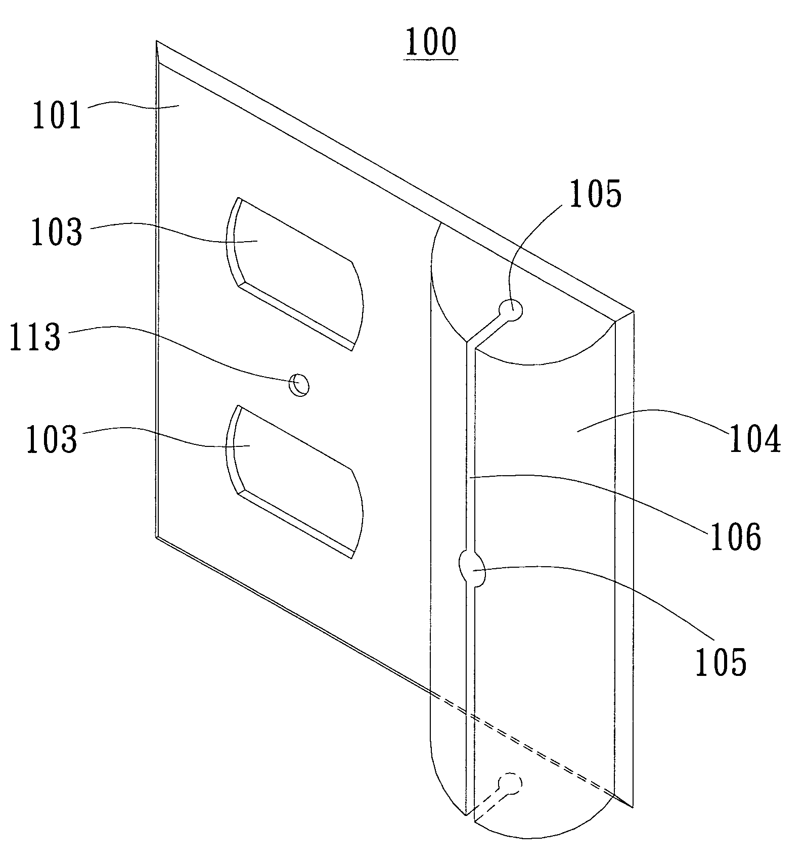
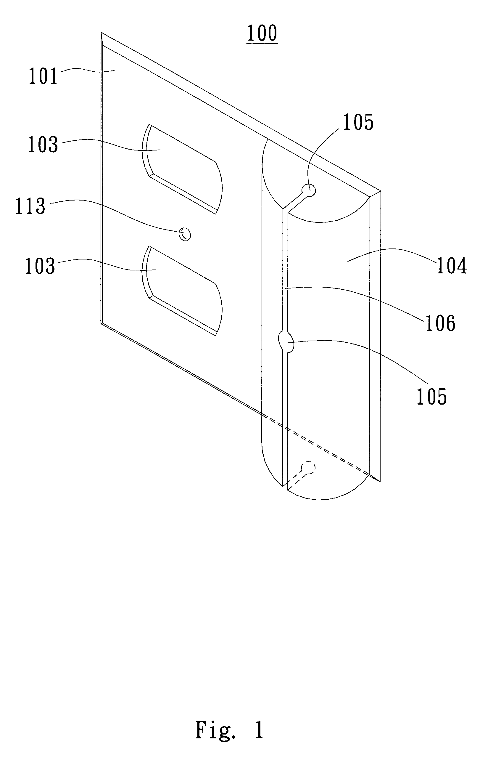
[0040]FIG. 1 shows a schematic diagram of an outlet cover 100 according to an embodiment of the present invention. The outlet cover 100 comprises an outlet surface 101 and a cord management container 104 protruding from the outlet surface 101. The outlet surface 101 has two outlet openings 103 formed on one half of the outlet surface 101, and the cord management container 104 is disposed corresponding to the outlet openings 103. In this embodiment, the cord management container 104 is disposed on the other half of the outlet surface 101 and on a side of the outlet openings 103. The cord management container 104 is close to the outlet opening 103 in order to reduce the length of the un-stored and exposed cord. The outlet surface 101 and the cord management container 104 of the...


PUM


Abstract

An outlet cover includes an outlet surface and a cord container for convenient cord storage is provided. The outlet surface has at least one outlet opening, and the cord container is disposed corresponding to the outlet opening. The above cord container has a plurality of cord entry / exit holes and at least one passage connecting the plurality of cord entry / exit holes. A power supply cover box includes a body and at least a cord container is also provided. The body includes a first end having at least one outlet opening. The cord container of the power supply cover box has a plurality of cord entry / exit holes and passages connecting the plurality of cord entry / exit holes. The passages have a predetermined width, which is preferably slightly smaller than the diameter of a regular electric cord, to retain the cord within the cord container. The cord container only allows the cord to enter or exit through the cord entry / exit holes.

Description

[0001]This application claims benefit to a provisional application No. 60 / 788,332 filed on Apr. 3, 2006, and to another provisional application No. 60 / 795,483 filed on Apr. 28, 2006.BACKGROUND OF THE INVENTION[0002]1. Field of the Invention[0003]The present invention relates generally to modified outlet covers, and more particularly to a power supply cover box with versatile features such as electrical outlets or USB ports, cord management containers and utility trays.[0004]2. Description of the Prior Art[0005]The historic discovery and generation of electricity has changed the way people lived significantly. Availability of electricity as well as reliable and effective electric power delivery system led to widespread use of various electric appliances and other devices. Yet an electric appliance is without value unless it is plugged into an electrical outlet for power connection. Consequently, as modern life gets more and more high-tech, electrical outlets have become an essential ...

Claims


Application Information

Patent Timeline
Patent Type & Authority Patents(United States)
IPC IPC(8): H01R13/72
CPCH01R13/72H02G3/14H01R25/006H04M1/04H02G11/00
Inventor WU, HSINHANALEXANDER, JEFFREY M.
Owner WU HSINHAN
Why Eureka
Try Eureka