Magnetic recording element, magnetic recording apparatus and recording method of information

a technology of magnetic recording apparatus and recording element, which is applied in the field of magnetic recording element, magnetic recording device and recording method of information, can solve the problems of difficult to say, unable to prevent cross-talk between adjacent cells, and appearing barriers in data writing styl

Inactive Publication Date: 2009-05-12
KK TOSHIBA
View PDF8 Cites 44 Cited by
  • Summary
  • Abstract
  • Description
  • Claims
  • Application Information

AI Technical Summary

Problems solved by technology

However, a demand for high density memory has reached 100 nm to several tens nm or a shorter scale as a unit cell for storing 1-bit data, so that technical barrier is appearing in data writing style.
Current magnetic field writing style also cannot prevent the cross talk to adjoining cells.
However, it is hard to say that the most commonly used magnetization switching by use of the spin-transfer torque sufficiently demonstrates its potential.
The current necessary for magnetization switching is extremely large, from 10 mA to several mA even in case where the cell size is 100 nm to several tens nm, so that the device may be damaged and this cannot satisfy the demand for lowered power consumption.
In summary, the current technology of the magnetization switching by use of the spin-transfer is not sufficient in light of current consumption and high-speed characteristics.

Method used


Image

  • Magnetic recording element, magnetic recording apparatus and recording method of information
  • Magnetic recording element, magnetic recording apparatus and recording method of information
  • Magnetic recording element, magnetic recording apparatus and recording method of information

Examples


first embodiment

(1) FIRST EMBODIMENT

[1-1] Structure

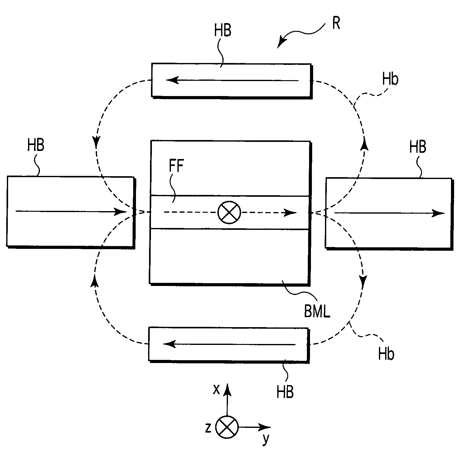
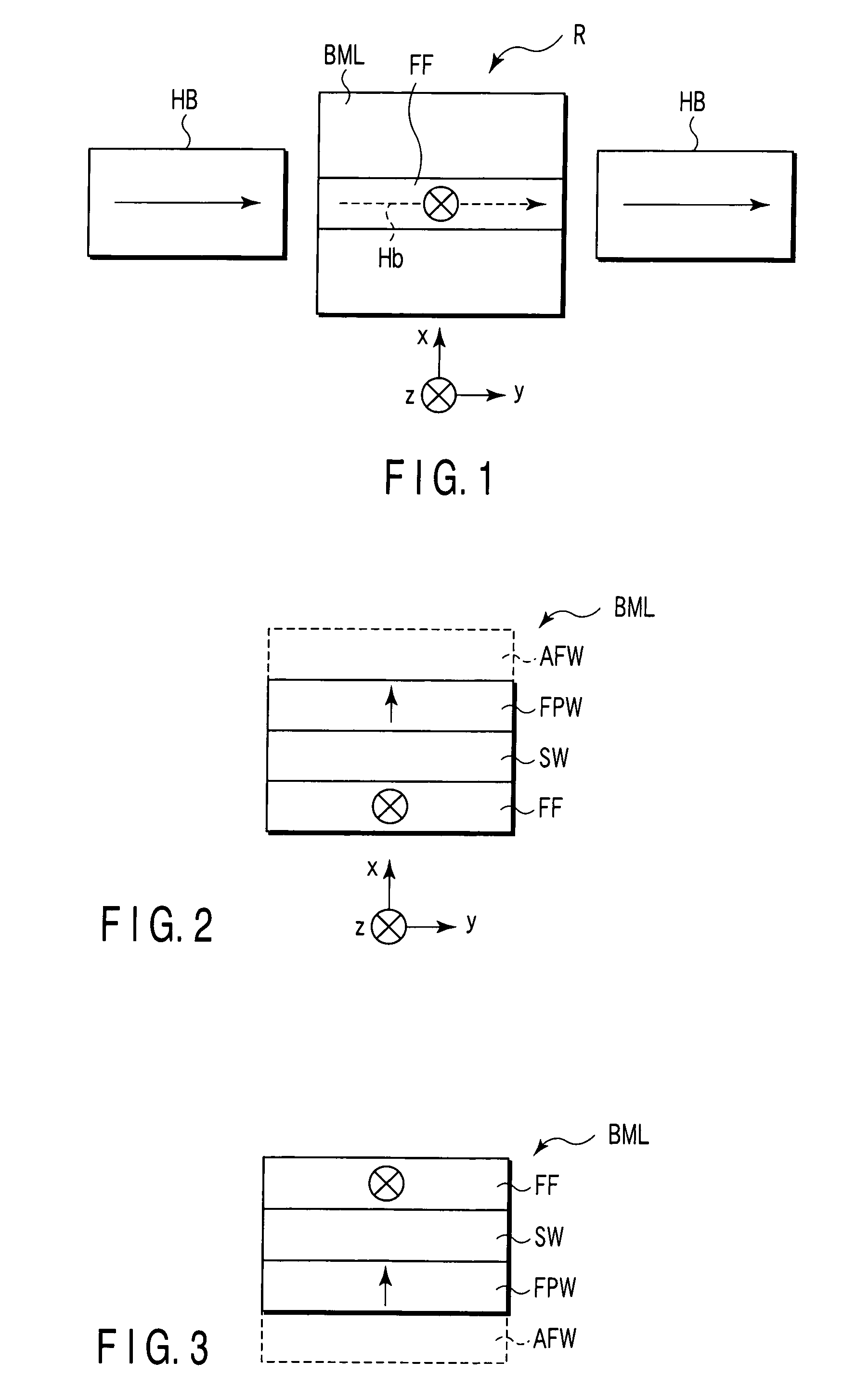
[0043]FIG. 1 is a schematic diagram showing the sectional structure of a magnetic recording element according to the first embodiment of the present invention. This magnetic recording element R comprises a lamination film BML called basic lamination film hereinafter below and hard bias layer (magnetic field generation layer) HB disposed near the basic lamination film BML. The hard bias layer HB and the basic lamination film BML are preferred to be insulated from each other magnetically and electrically with a nonmagnetic insulation film sandwiched thereby.

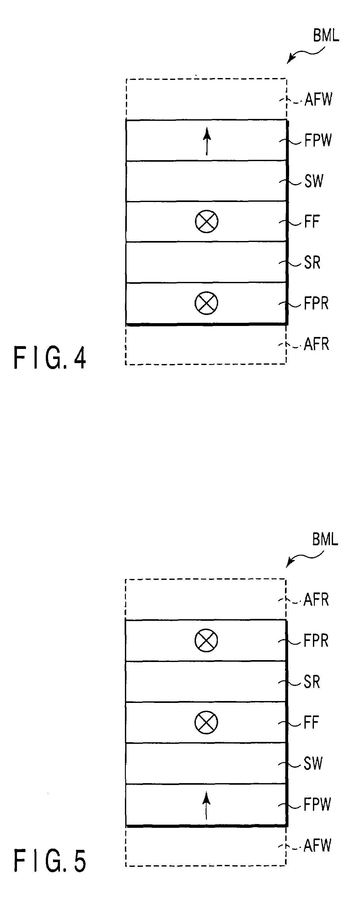
[0044]The basic lamination film BML contains ferromagnetic layer FF and more specifically, has a sectional structure expressed schematically by any one of FIGS. 2 to 5. In a description below, it is assumed that the film face of the basic lamination film BML spreads along z-y plane of a space composed of x-axis, y-axis and z-axis intersecting mutually. As shown in FIG. 2 or 3, in the basic laminat...

second embodiment

(2) SECOND EMBODIMENT

[0111]According to the second embodiment, the hard bias layer HB outside of the basic lamination film BML according to the first embodiment is added to the basic lamination film BML.

[2-1] Structure

[0112]FIGS. 50 and 51 schematically show the sectional structure of the magnetic recording element according to the second embodiment of the present invention. As shown in FIG. 50, the hard bias layer is provided at the bottom of the basic lamination film BML to contact with its bottom layer. In a structure shown in FIG. 51, the hard bias layer HB is provided at the top of the basic lamination film BML to contact with its top layer. The magnetization direction of the hard bias layer is the same as that of the hard bias layer HB having a structure shown in FIG. 42 or 43 of the first embodiment. This device is produced in the same manufacturing process as the magnetic recording element R of the first embodiment. As the structure and material of the basic lamination film ...

third embodiment

(3) THIRD EMBODIMENT

[0119]According to this embodiment, wiring is provided near the basic lamination film BML or a magnetic recording element including the basic lamination film BML and a current flowing through the wiring generates magnetic field for bias magnetic field.

[3-1] Structure

[0120]FIG. 52 is a perspective view showing schematically a memory cell according to the third embodiment of the present invention. As shown in FIG. 52, the memory cell comprises a magnetic recording element R containing the basic lamination film BML and wiring BL and wiring WL. The magnetic recording element R may be constituted of only the basic lamination film BML or have a structure in which the hard bias layer HB is added to the basic lamination film BML as shown in the second embodiment. Further, it may have a structure in which conductive films (not shown) are added above and below. The hard bias layer HB may be provided around the magnetic recording element R as indicated in the first embodime...


PUM


Abstract

A magnetic recording element includes a first fixed layer having a first and second face and having a magnetization direction fixed in a direction penetrating the first and second face. A free layer has a third and fourth face, a magnetization easy and hard axis both extending along the third or fourth face, and a magnetization direction which changes according to a direction of a current flowing through the first and fourth face with a magnetic field applied in a fixed direction or according to a direction of a magnetic field applied to the free layer with a current flowing through the first and fourth face in a fixed direction. A nonmagnetic first intermediate layer is provided between the second and third face. A magnetic field generating layer applies a magnetic field smaller than the anisotropy field of the free layer to the free layer along the magnetization hard axis.

Description

CROSS-REFERENCE TO RELATED APPLICATIONS[0001]This application is based upon and claims the benefit of priority from prior Japanese Patent Application No. 2004-368190, filed Dec. 20, 2004, the entire contents of which are incorporated herein by reference.BACKGROUND OF THE INVENTION[0002]1. Field of the Invention[0003]The present invention relates to a magnetic recording element, magnetic recording device and recording method of information, and more particularly to a magnetic recording element capable of controlling the magnetization direction of a magnetic substance by use of the spin-transfer torque so as to record data.[0004]2. Description of the Related Art[0005]Information recording apparatuses have been used to satisfy a variety of demands such as increased capacity, high speed, excellent durability, low cost as an existence which supports wide and highly information age society and leads it in recent years and technology for improving such features has been demanded. Of these ...

Claims


Application Information

Patent Timeline
Patent Type & Authority Patents(United States)
IPC IPC(8): G11C7/00
CPCG11C11/16
Inventor MORISE, HIROFUMINAKAMURA, SHIHOHANEDA, SHIGERUHIRAI, TAKAHIRO
Owner KK TOSHIBA
Why Eureka
Try Eureka