Straightening system

Inactive Publication Date: 2009-05-19
FRERICKS DONALD J
View PDF12 Cites 10 Cited by
  • Summary
  • Abstract
  • Description
  • Claims
  • Application Information

AI Technical Summary

Benefits of technology

[0014]It is therefore an object of the present invention to provide a new and improved straightening system which has all of the advantages of the prior art straightening systems of known designs and configurations and none of the disadvantages.
[0015]It is another object of the present invention to provide a new and improved straightening system which may be easily and efficiently manufactured and marketed.
[0016]It is further object of the present invention to p

Problems solved by technology

While these devices fulfill their respective, particular objectives and requirements, the aforementioned patents d

Method used


Image

  • Straightening system
  • Straightening system
  • Straightening system

Examples


Example

[0030]The same reference numerals refer to the same parts throughout the various Figures.

DESCRIPTION OF THE PREFERRED EMBODIMENT

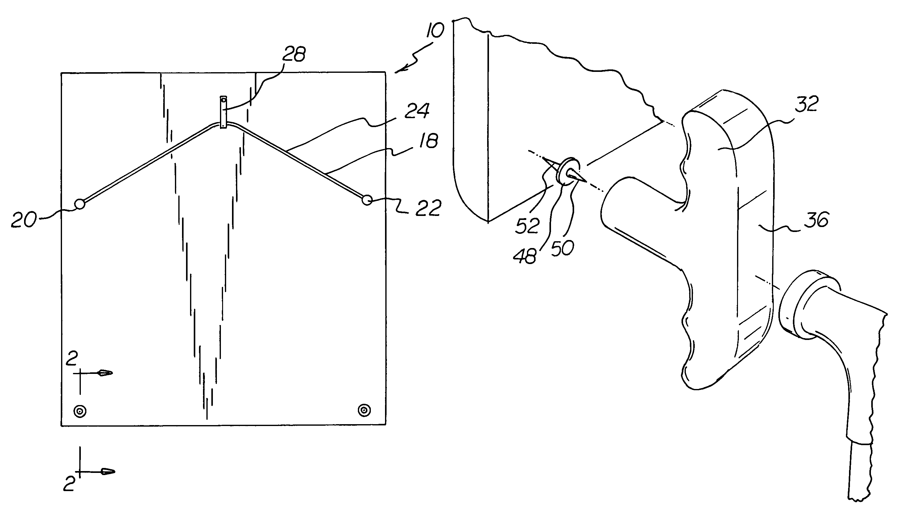
[0031]With reference now to the drawings, and in particular to FIG. 1 thereof, the preferred embodiment of the new and improved straightening system embodying the principles and concepts of the present invention and generally designated by the reference numeral 10 will be described.

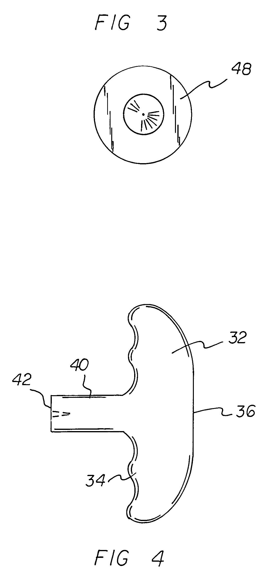
[0032]The present invention, the straightening system 10 is comprised of a plurality of components. Such components in their broadest context include a handle and a pin assembly. Such components are individually configured and correlated with respect to each other so as to attain the desired objective.

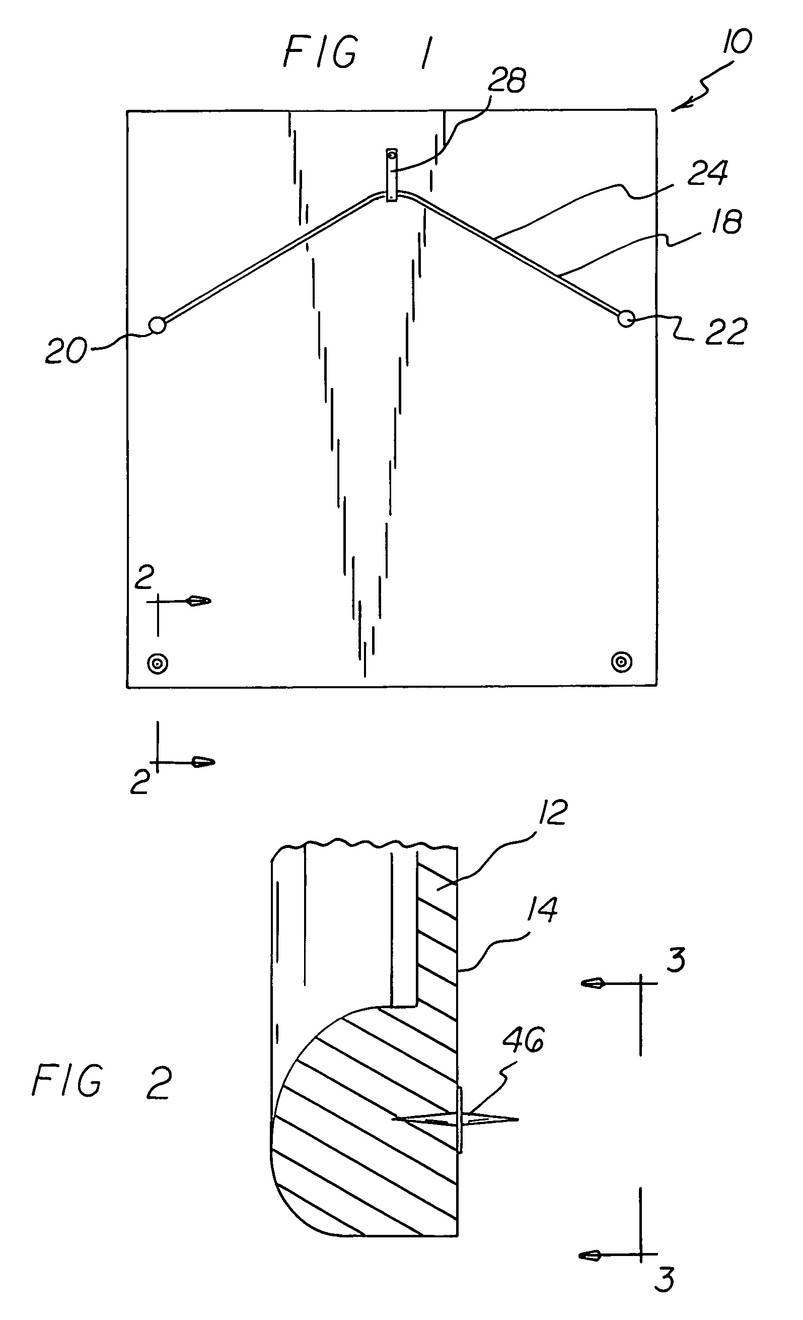
[0033]First provided is an object 12 having a back panel 14 adapted to face a wall.

[0034]Next, a hanging assembly 18 is provided. The hanging assembly has a first screw 20 adapted to be attached to a left half of the back panel and a second screw 22 adapted to be attached to the rig...


PUM


Abstract

A straightening system has a handle formed of a rigid material. The handle has a gripping portion in a generally cylindrical configuration adapted to be held by a hand of a user and a support portion in a generally cylindrical configuration extending at right angles from a central extent of the gripping portion. The support portion terminates in a flat region remote from the gripping portion. A pin assembly couples an object to a wall to insure proper positioning and retention of the proper positioning. The pin assembly has a circular disc-shaped center with an axis parallel with the axis of the support portion. The pin assembly has at least one outwardly extending pin for positioning in the wall adjacent an object and an inwardly directed attachment member for positioning with respect to the object.

Description

BACKGROUND OF THE INVENTION[0001]1. Field of the Invention[0002]The present invention relates to a straightening system and more particularly pertains to insuring that objects are hung or retained in a proper orientation.[0003]2. Description of the Prior Art[0004]The use of straightening systems of known designs and configurations is known in the prior art. More specifically, straightening systems of known designs and configurations previously devised and utilized for the purpose of hanging and retaining objects in proper orientation are known to consist basically of familiar, expected, and obvious structural configurations, notwithstanding the myriad of designs encompassed by the crowded prior art which has been developed for the fulfillment of countless objectives and requirements.[0005]By way of example, U.S. Pat. No. 5,454,542 to Hart discloses Apparatus and Methods for Hanging Frames. U.S. Pat. No. 6,186,466 to Baird et al. discloses a Hanging Frame Stabilizer. U.S. Pat. No. 2,...

Claims


Application Information

Patent Timeline
IPC IPC(8): A47G1/16
CPCA47G1/168
Inventor FRERICKS, DONALD J.
Owner FRERICKS DONALD J
Why Eureka
Try Eureka