Modular trolling motor control system

a control system and trolling motor technology, applied in the direction of motor/generator/converter stopper, dynamo-electric converter control, steering initiation, etc., can solve the problems of complex control system for controlling the operation of trolling motors, becoming more sophisticated and complex

Active Publication Date: 2009-05-26
JOHNSON OUTDOORS
View PDF17 Cites 71 Cited by
  • Summary
  • Abstract
  • Description
  • Claims
  • Application Information

AI Technical Summary

Problems solved by technology

Control systems for controlling the operation of a trolling motor have become more sophisticated and more complex.

Method used


Image

  • Modular trolling motor control system
  • Modular trolling motor control system
  • Modular trolling motor control system

Examples


Embodiment Construction

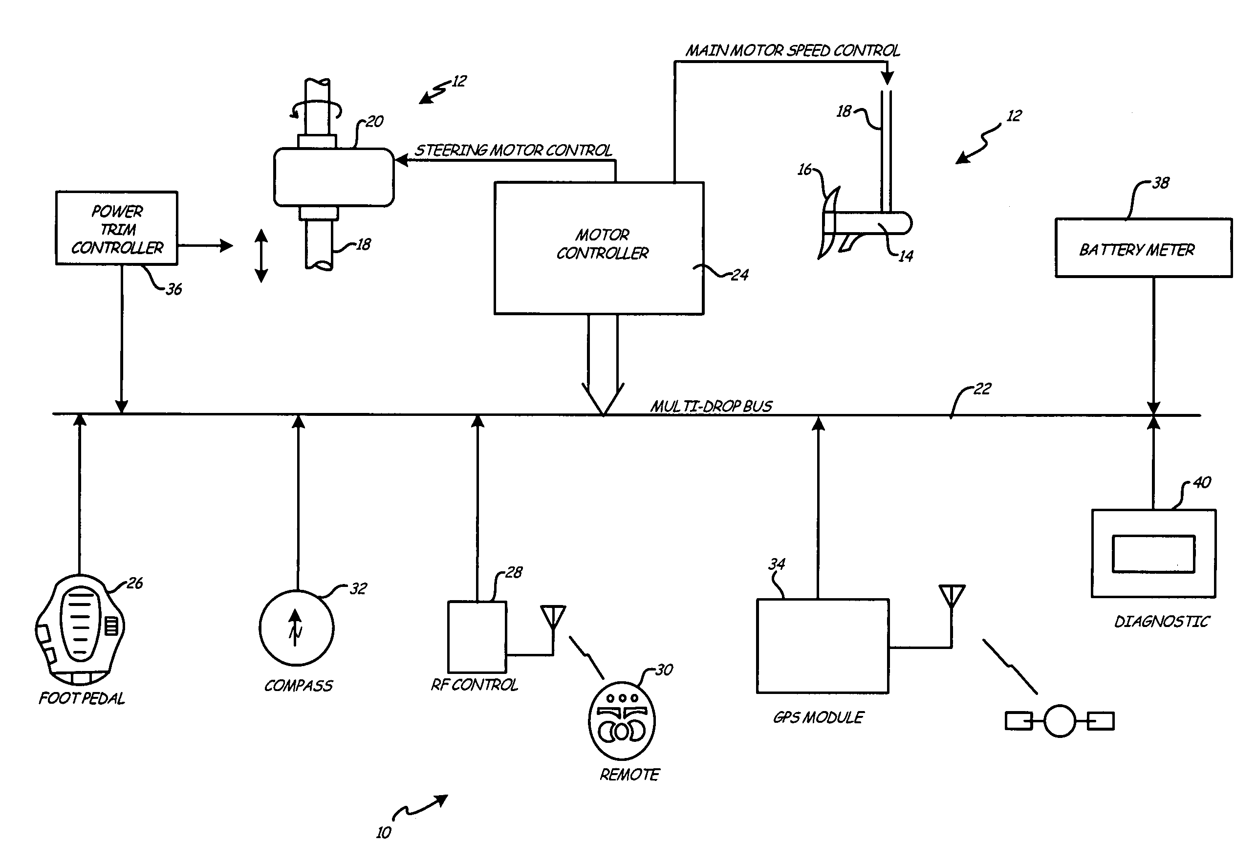
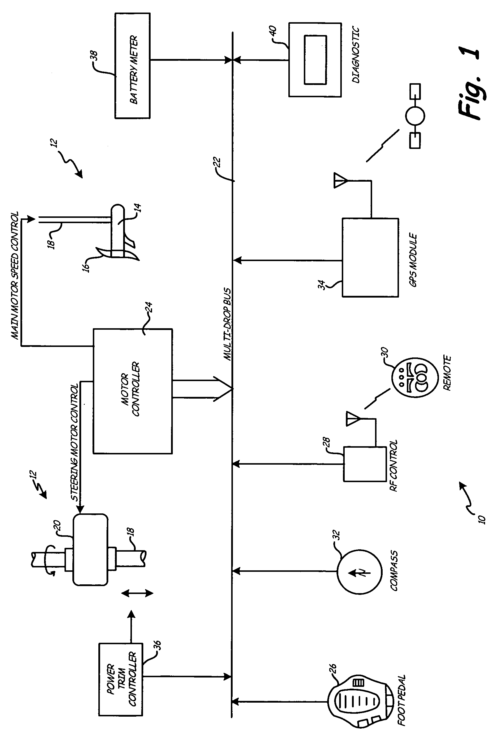
[0012]FIG. 1 shows a block diagram of modular trolling motor control system 10, which controls the operation of electric trolling motor 12. As shown in FIG. 1, trolling motor 12 includes main thrust motor 14 with propeller 16, shaft 18 and steering motor 20. Main motor 14 is mounted at the lower end of shaft 18. Steering motor 20 rotates shaft 18 to turn main motor 14 to direct thrust in order to steer the boat.

[0013]Modular system 10 is a networked system, in which modules are connected to multidrop communication bus 22. In the embodiment shown in FIG. 1, control system 10 includes motor controller module 24, foot pedal module 26, RF control module 28, remote control 30, compass module 32, GPS module 34, power trim controller module 36, battery meter module 38, and diagnostic module 40.

[0014]Communication bus 22 is, for example, an RS 485 bus that provides bi-directional communication among the modules that are connected to it. Each module has a connector or multiple connectors tha...


PUM


Abstract

A trolling motor control system includes plurality of modules that are connected to a communication bus to transmit and receive data used in controlling operation of a trolling motor. Based upon data transmitted over the bus, trolling motor speed, steering, and trim can be controlled. The modules can include motor controller modules, foot pedal modules, compass and GPS modules, RF modules for wireless control, battery metering modules, diagnostic modules, accessory device driver modules, power trim controller modules, and power steering controller modules.

Description

BACKGROUND OF THE INVENTION[0001]The present invention relates to trolling motors. In particular, the present invention relates to a modular control system including multiple modules connected in a network over a communication bus for controlling operation of a trolling motor.[0002]Fishing boats are often equipped with a trolling motor for providing a relatively small amount of thrust to slowly and quietly propel the boat while the operator is fishing. Most outboard trolling motors are battery powered and are mounted to either the bow or the stem of the boat.[0003]Trolling motors can be manually operated using a tiller to rotate the trolling motor in order to steer the boat, and to control the speed of the trolling motor. Other trolling motors make use of a wired foot pedal to control steering, to turn the propeller on and off, and to control the trolling motor speed. Wireless controls have also been developed using wireless communication from a foot pedal or from a small hand held ...

Claims


Application Information

Patent Timeline
Patent Type & Authority Patents(United States)
IPC IPC(8): G05D1/00
CPCB63H20/007B63H21/213G05D1/0206
Inventor SAMEK, DAVID M.
Owner JOHNSON OUTDOORS
Why Eureka
Try Eureka