Mobile support assembly

a mobile support and assembly technology, applied in the direction of wheelchair/patient conveyance, wheelchair/perambulator with multiple axes, foldable cycles, etc., can solve the problems of lessening the stability of the walker, affecting the mobility of the walker, and requiring more sophisticated wheelchair designs, so as to facilitate the disposition of the individual, enhance the versatility of the mobile support assembly, and facilitate access to the chair assembly

Active Publication Date: 2009-06-02
DRIVE MEDICAL CANADA INC
View PDF124 Cites 27 Cited by
  • Summary
  • Abstract
  • Description
  • Claims
  • Application Information

AI Technical Summary

Benefits of technology

[0012]In addition, yet another preferred embodiment of the present invention comprises the walker assembly including a front wheel assembly connected to the front leg assembly and a rear wheel assembly connected to the rear leg assembly. Additional structural features associated with the front and rear wheel assemblies are their ability to be selectively disposed in a position which reduces at least the longitudinal dimension and overall configuration of the walker assembly when in a stored orientation. More specifically, the various embodiments of a walker assembly of the present invention include the front wheel assembly being removably secured to the front leg assembly. Similarly, the rear wheel assembly can be connected to at least a portion of the rear wheel assembly such that it is movable therewith into and out of a folded storage position. Alternatively, the rear wheel assembly may be disconnected from the rear leg assembly. In either structural variation the configuration and at least the longitudinal dimension of the frame of the walker assembly is further reduced in order to facilitate storage and transport of the walker assembly.
[0021]The mobile support assembly of this preferred embodiment of the present invention may have similar structural and operative features as the previously described preferred embodiments. More specifically, added versatility of the mobile support assembly is enhanced by the aforementioned handle assembly being adjustably and removably connected to a remainder of the frame. As such, the height of the handle assembly may be selectively adjusted to accommodate different individuals or it may be removed to facilitate storage, regardless of the mobile support assembly being used as a walker or wheelchair. Also, hand operated brakes may be mounted on or connected to the handle assembly so as to be readily accessible from the hand grips or handlebar of each of the handles. Operative interconnection between the hand applied brake members and the wheel assembly is accomplished by appropriate mechanical linkage, such as a cable or the like.

Problems solved by technology

Also, conventionally structured walkers may or may not include supporting wheel assemblies.
However, the presence of such wheel assemblies, depending on their structural features and also on whether or not there is safety measures associated therewith, may lessen the stability of the walker.
However, the collapsibility of conventional walkers may be limited in that the walker still must offer sufficient structural integrity as well as provide adequate stability and support to an individual when in use.
In addition, more sophisticated wheelchair designs are motorized and while more expensive, they are still relatively common.
Despite the advantages of the type set forth above, the larger more sophisticated wheelchair structures do have certain disadvantages relating to the storage and transport thereof when not in use.
However, many collapsible wheelchair structures still assume a bulky configuration even when in a folded orientation, thereby requiring a significant amount of space when stored or loaded into the trunk or other appropriate location of a vehicle.
However, there appears to be an absence of a combined structure having multi-use capabilities such that a single mobile support assembly may be utilized as both a walker and a wheelchair by assuming different orientations of the structural components of which such an assembly is comprised.

Method used


Image

  • Mobile support assembly
  • Mobile support assembly
  • Mobile support assembly

Examples


Embodiment Construction

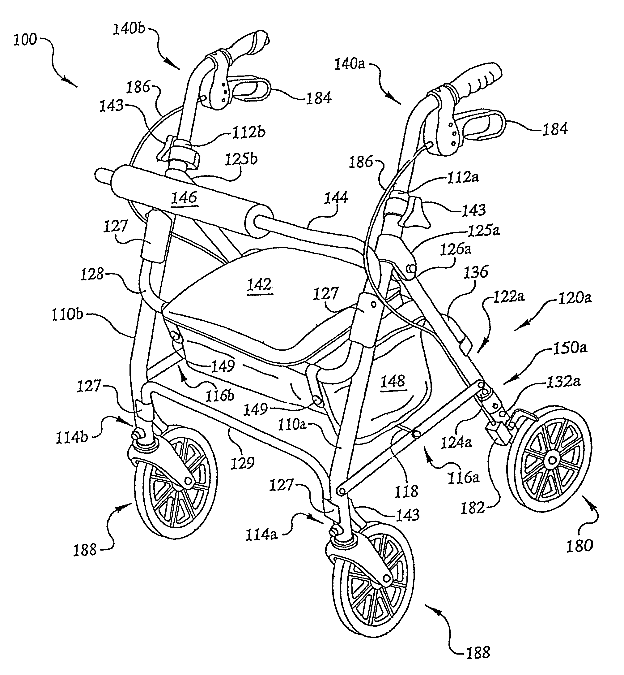
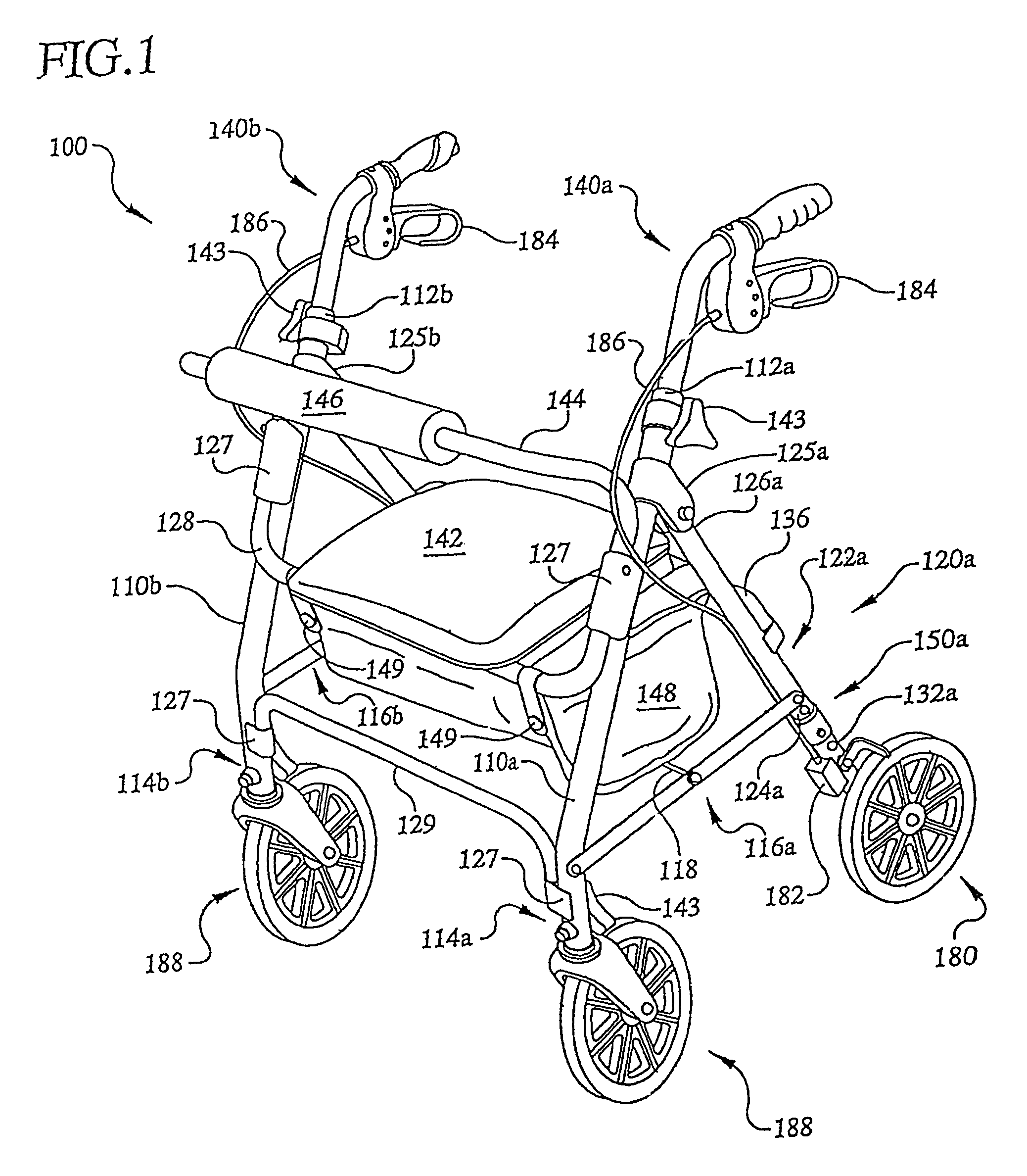
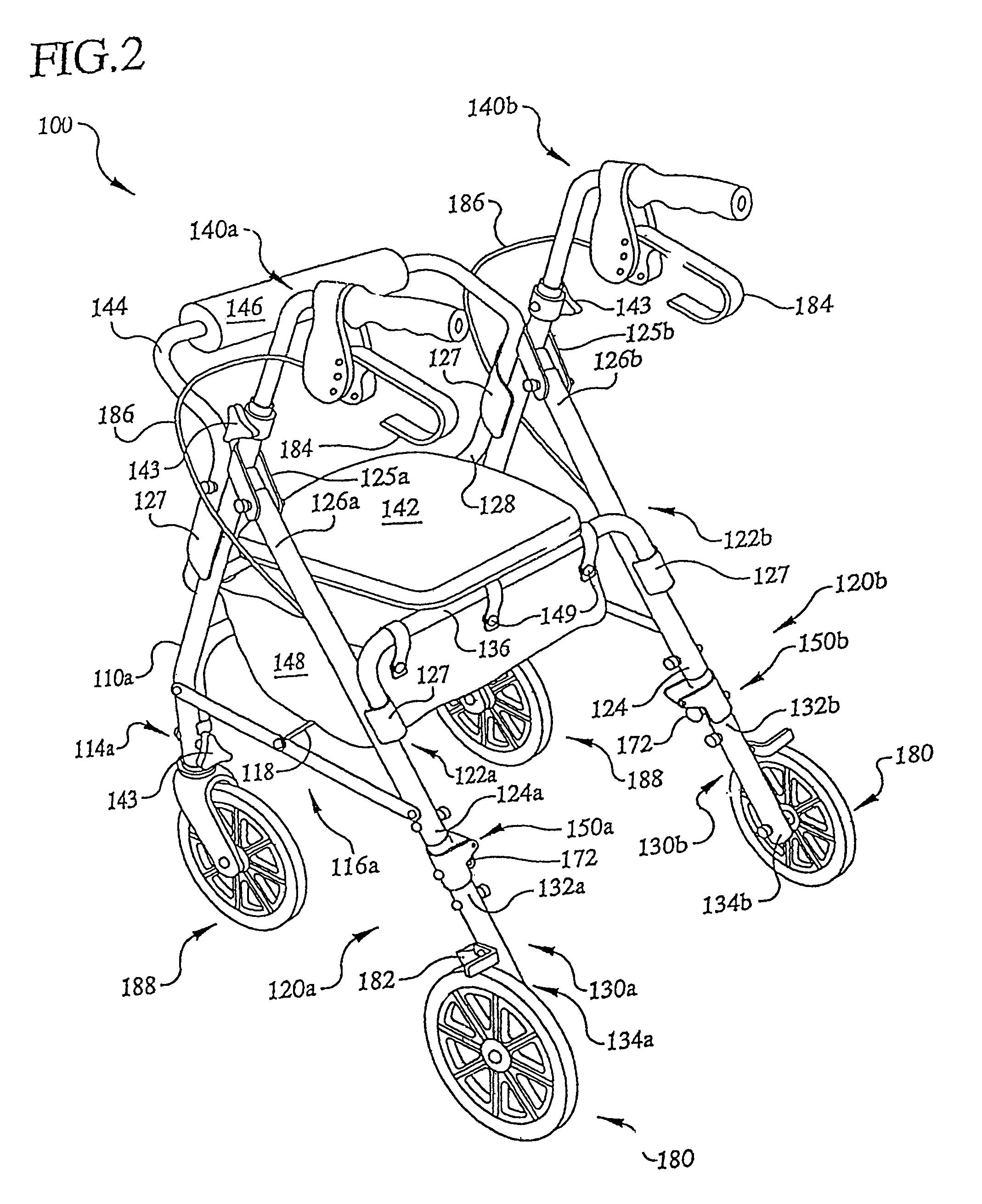
[0049]Referring now in more detail to the drawings, FIGS. 1-3 illustrate an embodiment of a foldable walker 100 in an operative orientation. As shown, the foldable walker 100 comprises a frame at least partially defined by a front leg assembly and a rear leg assembly. More specifically, the front leg assembly comprises a first front leg 110a and a second front leg 110b secured to each other by at least a first cross member 128. The first front leg 110a and a second front leg 110b are each pivotally connected to the rear leg assembly, which comprises a first rear leg 120a and a second rear leg 120b, respectively. The first and second rear legs 120a, 120b each include an upper member or portion 122a, 122b, which in at least one preferred embodiment, are hingedly attached to a respective lower member or portion 130a, 130b by hinge assemblies 150a, 150b, respectively, as is discussed in greater detail hereinafter. Preferably, the first upper member 122a and a second upper member 122b ar...


PUM


Abstract

A multi-use mobile support assembly structured to be selectively used as a walker or a wheelchair including a frame having at least one adjustable frame segment structured to be disposed in either a first orientation or a second orientation. The frame may be foldable and includes at least a first front leg and at least a first rear leg, having wheel assemblies connected thereto for travel of the frame, whether used as a walker or wheelchair, over a different ground or support surfaces. In one embodiment, the first rear leg includes an upper member having a first end a second end and a lower member having a first end and a second end. The first end of the upper member may be pivotally connected to the first end of the lower member, and the lower member is removable with a corresponding wheel assembly or pivotal between an extended use position and a folded storage position.

Description

[0001]The present invention is a continuation-in-part application of previously filed, application having Ser. No. 11 / 129,569, filed on May 13, 2005 now U.S. Pat. No. 7,066,484, which is a continuation-in-part application of previously filed, application having Ser. No. 10 / 680,596, filed on Oct. 7, 2003 now U.S. Pat. No. 7,073,801, both incorporated herein in their entirety, by reference.BACKGROUND OF THE INVENTION[0002]1. Field of the Invention[0003]This invention is directed to a mobile support assembly which is structured to be selectively disposed in either a first orientation, wherein the assembly may be used as a walker or in a second orientation wherein the assembly may be used as a wheelchair. Various preferred embodiments of the mobile support assembly facilitate the selective and relative disposition of the various components thereof into a folded, collapsed position for storage, shipment, etc. when not in use. In addition, certain of the structural components may be varia...

Claims


Application Information

Patent Timeline
Patent Type & Authority Patents(United States)
IPC IPC(8): A61H3/04
CPCA61G5/08A61H3/04A61G2005/0833A61G2005/0866A61G2005/0883A61G2005/0891A61G2005/125A61G2005/128A61H2003/046A61H2201/0161A61H2201/1633A61G5/0833A61G5/0866A61G5/0883A61G5/0891A61G5/125A61G5/128
Inventor WILLIS, PHILLIP MINYARDBERNARD, RANDY
Owner DRIVE MEDICAL CANADA INC
Why Eureka
Try Eureka