Computer case retention structure

a technology for computer cases and retention structures, applied in the field of computer cases, can solve problems such as the negative influence of the fixing of the cover, and achieve the effects of reducing the frequency of the bent elastic retention elements, preventing over-pressing, and prolonging the life of elastic retention elements

Inactive Publication Date: 2009-06-02
LITE ON TECH CORP
View PDF15 Cites 15 Cited by
  • Summary
  • Abstract
  • Description
  • Claims
  • Application Information

AI Technical Summary

Benefits of technology

[0009]In the prior art, the approach of fixing the cover to the base provides an elastic hook disposed on the cover for being engaged with a fixing element disposed on the base, the fatigue of material and permanent deformation of the elastic hook may occur with frequently repeated pressing or over-pressing acted on the elastic hook, thus the fixing of the cover is negatively affected. In view of the above problems, the object of the present invention is to provide a computer case retention structure for reducing the frequency of the elastic retention elements being bent, and preventing over-pressing from being acted on the elastic retention elements. Thereby, the lifetime of the elastic retention elements is prolonged, and thus the desirable retention effect also can be remained after repeated pressing acted on the elastic retention elements for a long time.
[0011]The benefit of the present invention is in that the first elastic blade is prevented from being frequent bent when the cover is fixed onto the base, due to the cooperation of the first and second elastic blades. According to the frequency and degree of being bent of the first elastic blade is reduced, the time for the fatigue of material and permanent deformation of the first elastic blade occurring is delayed. And the lifetime of the first elastic blade is effectively prolonged. Also, the appearance of the cover is maintained.

Problems solved by technology

In the prior art, the approach of fixing the cover to the base provides an elastic hook disposed on the cover for being engaged with a fixing element disposed on the base, the fatigue of material and permanent deformation of the elastic hook may occur with frequently repeated pressing or over-pressing acted on the elastic hook, thus the fixing of the cover is negatively affected.

Method used


Image

  • Computer case retention structure
  • Computer case retention structure
  • Computer case retention structure

Examples


Embodiment Construction

[0021]To further understand the objects, structures, features, and functions of the present invention, it is illustrated in great detail below with reference to the embodiments.

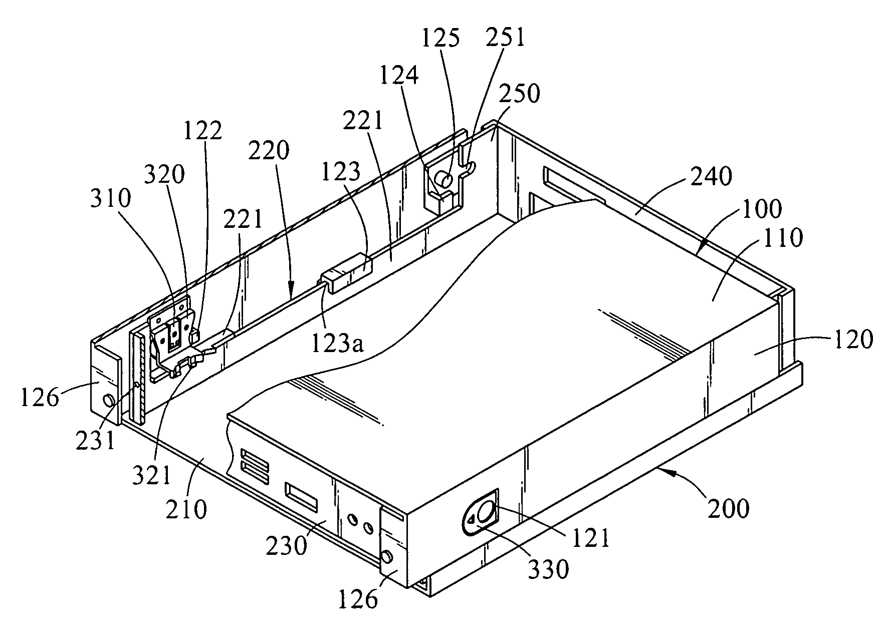
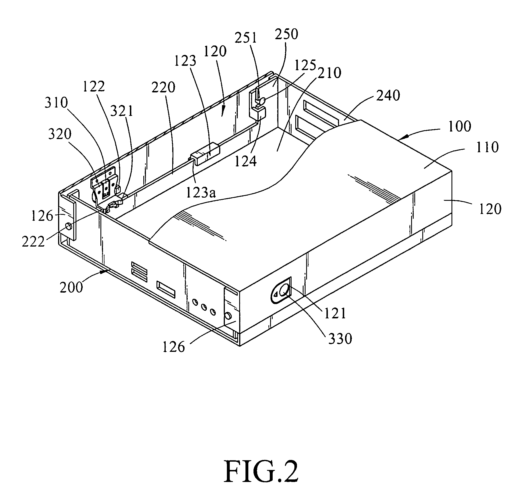
[0022]Referring to FIGS. 2, 3, 4, 5, and 6, a computer case retention structure according to the preferred embodiment of the present invention is shown, which includes a cover 100 and a base 200.

[0023]The cover 100 has a top plate 110 and two opposite side plates 120, the side plates 120 are perpendicularly extended from opposite edges of the top plate 110 respectively. An opening 121 is formed on each of the side plate 120 of the cover 100. A first elastic blade 310 and a second elastic blade 320 are disposed on the inner surface of each side plate 120, wherein one end of the first and second elastic blades 310 and 320 is fixed to the inner surface of the side plate 120, and the other end is suspended from the inner surface of the side plate 120 and exposed on the opening 121, swinging freely. In this embodi...


PUM


Abstract

A computer case retention structure includes a cover and a base. The base has a bottom plate and a guided way with a protruding hook. The cover has at least one side plate, a first and second elastic blades are disposed on the side plate. A protrusion is extended downward from a tip of the second elastic blade to slide against the guided way. For fixing the cover onto the base, the protrusion slides over the protruding hook and then stopped by the protruding hook, so that the cover is fixed onto the base without being moved relative to the base. For removing the cover, a release element disposed on the first elastic blade is pressed to bend the first and second elastic blades, separating the protrusion from the guided way. Then the cover can be removed from the base without the protrusion being stopped.

Description

CROSS-REFERENCE TO RELATED APPLICATIONS[0001]This non-provisional application claims priority under 35 U.S.C. § 119(a) on Patent Application No(s). 094131834 filed in Taiwan, R.O.C. on Oct. 5, 2005, the entire contents of which are hereby incorporated by reference.BACKGROUND OF THE INVENTION[0002]1. Field of Invention[0003]The present invention relates to a computer case, and more particularly, to a computer case retention structure for fixing a cover to a base.[0004]2. Related Art[0005]The case of the conventional horizontal-type computer is formed by a cover and a base. The cover has a top plate and two side plates, wherein the two side plates are perpendicular to bottom plate and extended from two opposing edges thereof. The base has a bottom plate, a front plate, and a back plate. When the cover is placed on the base, the two side plates, the front plate, and the back plate form a containing space between the top and bottom plates. Electronic devices of the computer, for example...

Claims


Application Information

Patent Timeline
Patent Type & Authority Patents(United States)
IPC IPC(8): H05K7/00
CPCG06F1/181
Inventor MAU, SHU-HUA
Owner LITE ON TECH CORP
Why Eureka
Try Eureka