

Self-suturing anchor device
a self-suturing and anchoring technology, applied in the field of catheters, can solve the problems of bending catheters, catheter pulling at the suture site, and affecting the suture, and achieve the effect of minimizing the disruption of sutures
- Summary
- Abstract
- Description
- Claims
- Application Information
AI Technical Summary
Benefits of technology
Problems solved by technology
Method used
Image

Examples
Embodiment Construction
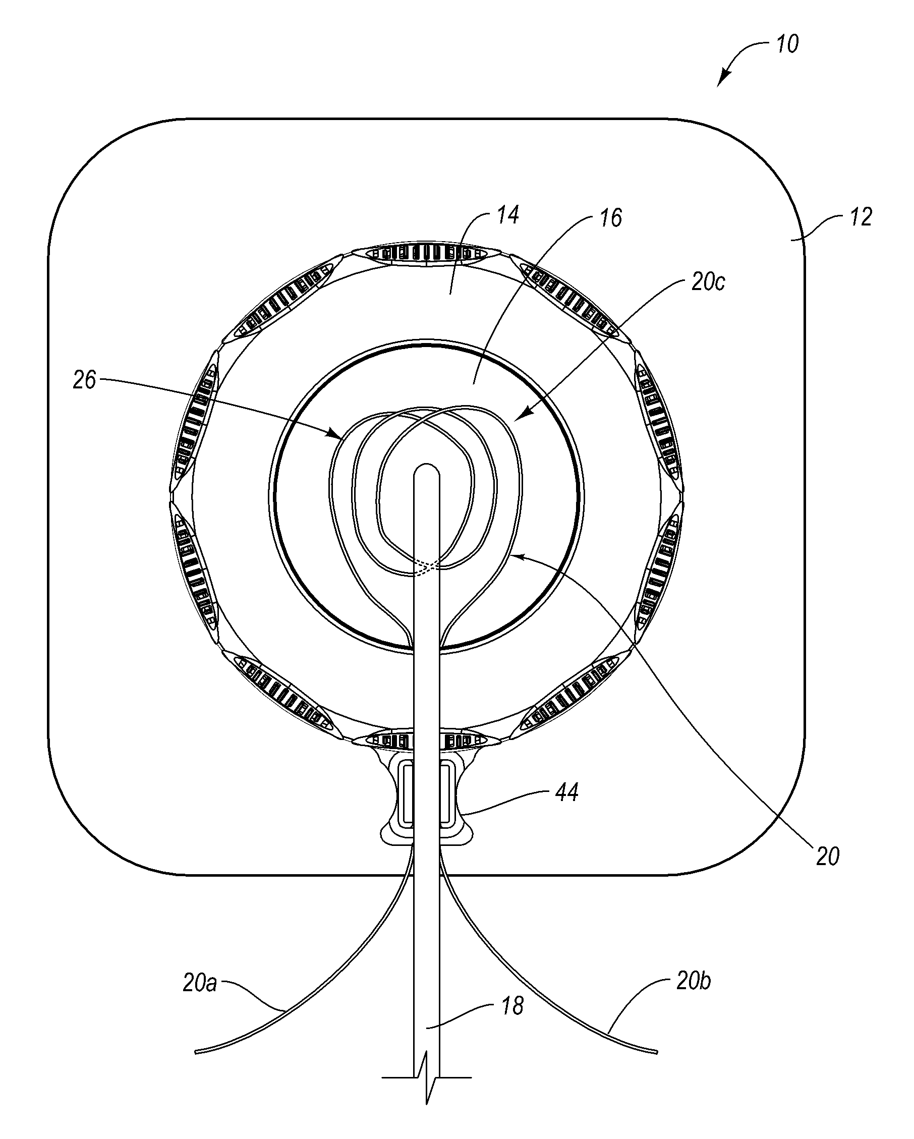
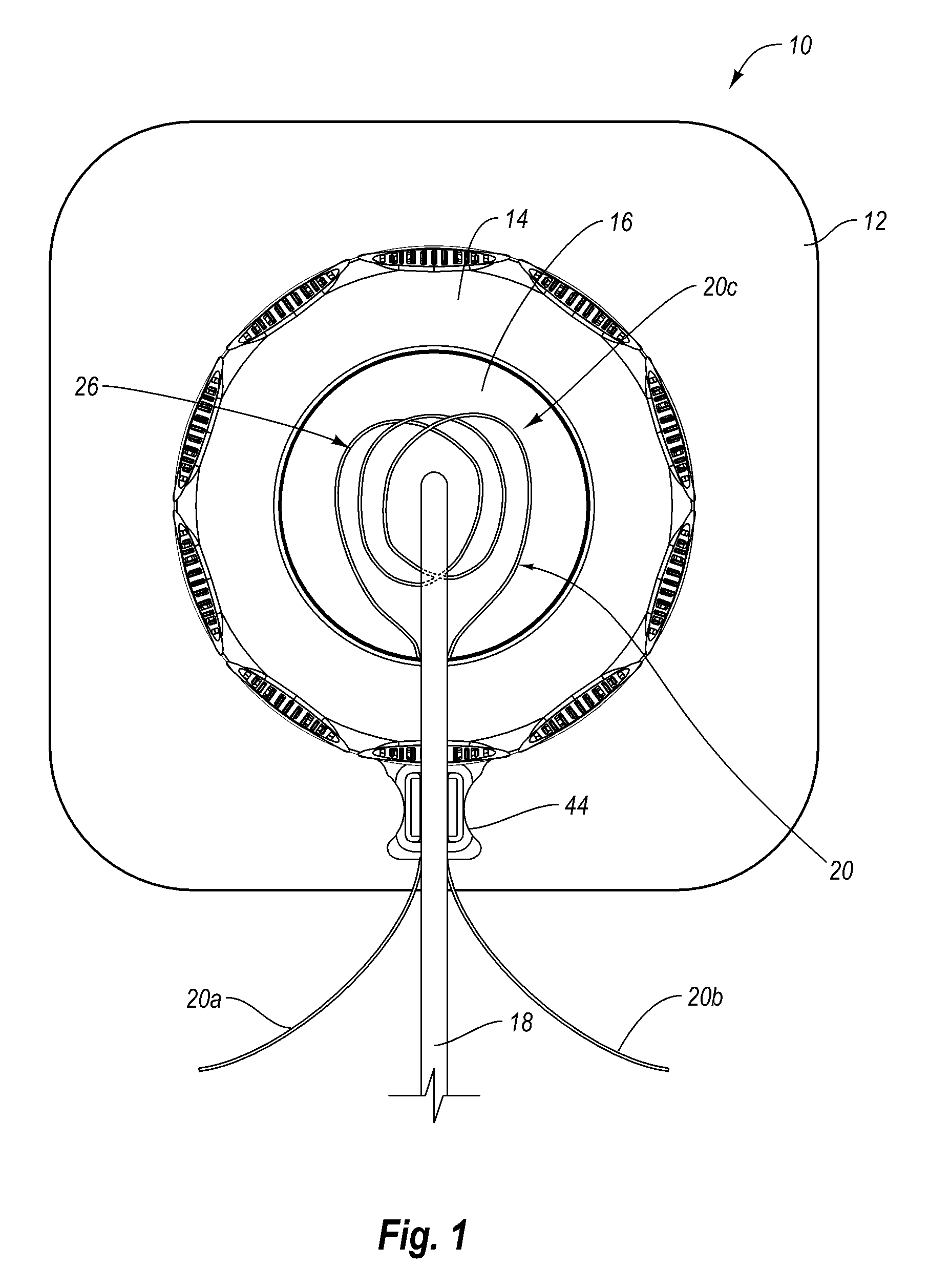
[0009]The present invention is directed to a catheter securement device that automatically secures the catheter without requiring the practitioner to manually suture the catheter to the self-suturing anchor device. According to one embodiment, the catheter securement device includes a center aperture defined in a rotatable ring. The catheter extends through the aperture when the catheter securement device is deployed. One or more sutures are disposed about the center aperture. As a result, when the catheter securement device is in place, the suture or sutures are located around the catheter. According to one example, the first suture is looped around the catheter and includes a knot tied therein.
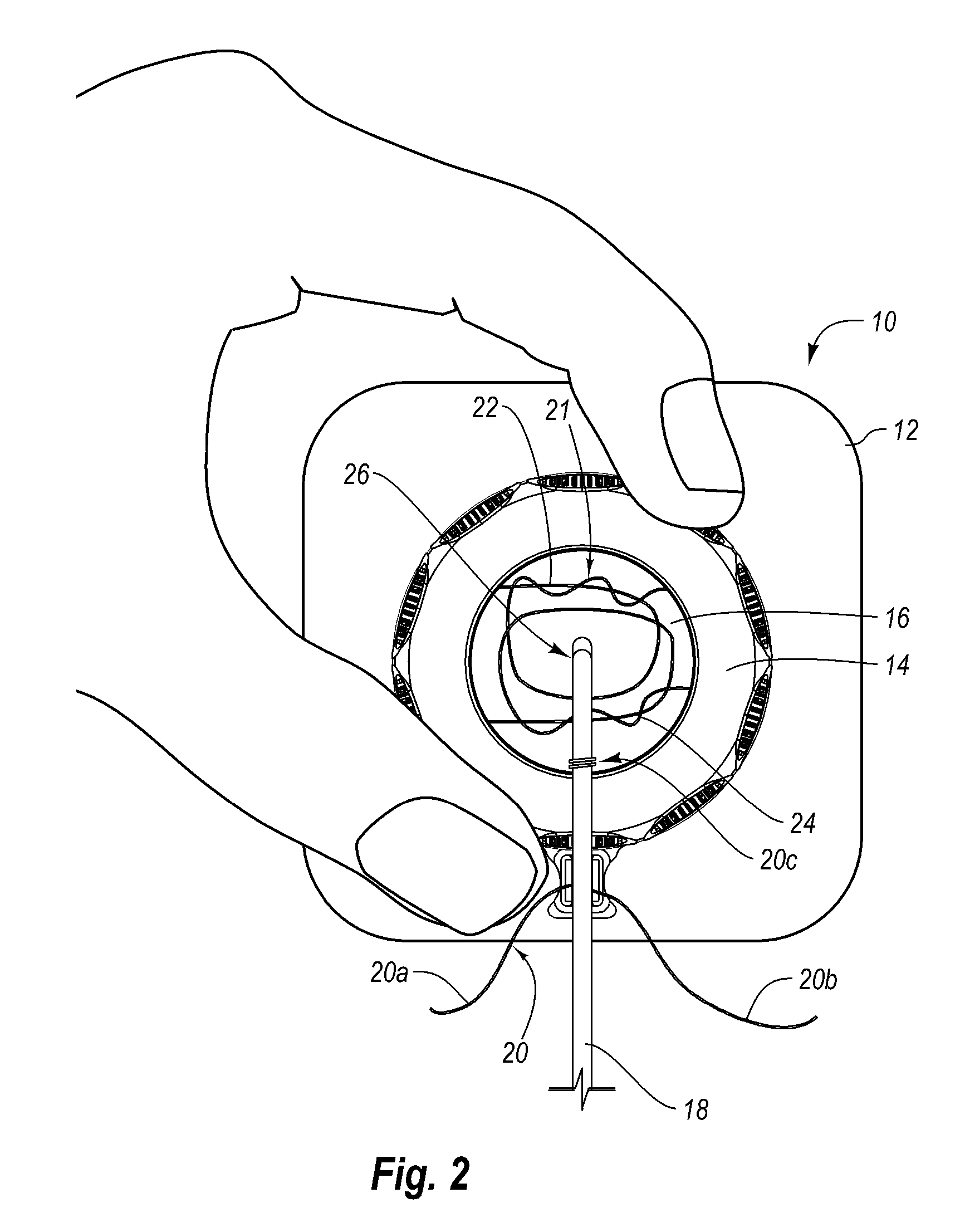
[0010]The catheter securement device may be secured to the patient with an adhesive. The adhesive allows a practitioner to rapidly locate the catheter securement device on the patient near the catheter insertion location. With the catheter securement device in place, a first securement is re...
PUM
 Abstract
Description
Claims
Application Information