Computer graphics shader systems and methods

a shader system and computer graphics technology, applied in the field of computer graphics and computer-aided design, can solve the problems of limiting the flexibility of shaders, limiting the ability of shaders to render features in an interesting and life-like manner, and using shaders

Inactive Publication Date: 2009-06-16
MENTAL IMAGES
View PDF10 Cites 91 Cited by
  • Summary
  • Abstract
  • Description
  • Claims
  • Application Information

AI Technical Summary

Benefits of technology

[0016]The present invention, various aspects of which are herein collectively termed “Mental Mill”, addresses the above-mentioned limitations of the prior art, and provides platform-independent methods and systems that can unite various shading applications under a single language (herein termed the “MetaSL shading language”), enable the simple re-use and re-purposing of shaders, facilitate the design and construction of shaders without need for computer programming, enable the graphical debugging of shaders, and accomplish many other useful functions.
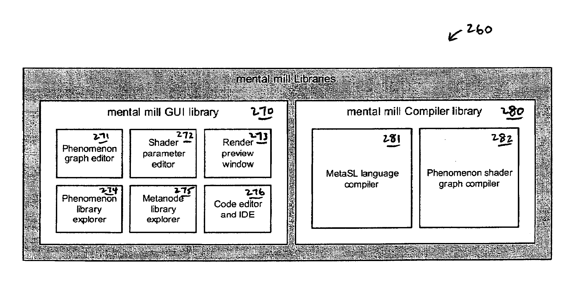
[0017]One aspect of the invention involves methods and systems that facilitate the creation of simple and compact componentized shaders, referred to herein as Metanodes, that can be combined in shader networks to build more complicated and visually interesting shaders.
[0019]The Mental Mill thus enables the creation of Metanodes (i.e., shader blocks) written in MetaSL, that can be attached and combined to form sophisticated shader graphs and phenomena.
[0020]The shader graphs provide intuitive graphical user interfaces for creating shaders, which are accessible even to users lacking technical expertise to write shader software code.

Problems solved by technology

A number of problems arise from the generation and use of shaders and shade trees as typically provided in computer graphics arrangements.
First, shaders generally cannot cooperate with each other unless they are programmed to do so.
Typically, input values provided to shaders are constant values, which limits the shaders' flexibility and ability to render features in an interesting and life-like manner.
In addition, it is generally difficult to set up systems of cooperating shaders which can get their input values from a common source.
This platform dependence typical of conventional shader systems and languages can be a significant limitation.

Method used


Image

  • Computer graphics shader systems and methods
  • Computer graphics shader systems and methods
  • Computer graphics shader systems and methods

Examples


Embodiment Construction

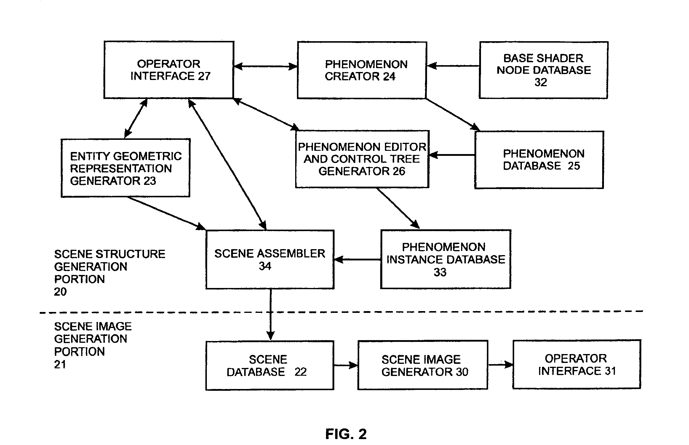
[0101]The present invention provides improvements to the computer graphics entity referred to as a “phenomenon”, which was described in commonly owned U.S. Pat. No. 6,496,190 incorporated herein by reference. Accordingly, we first discuss, in Section I below, the various aspects of the computer graphics “phenomenon” described in U.S. Pat. No. 6,496,190, and then, in Section II, which is subdivided into four subsections, we discuss the present improvements to the phenomenon entity.”

Section I. Computer Graphics “Phenomena”

[0102]U.S. Pat. No. 6,496,190 described a new computer graphics system and method that provided enhanced cooperation among shaders by facilitating generation of packaged and encapsulated shader DAGS, each of which can include one or more shaders, generated in a manner so as to ensure that the shaders in the shader DAGs can correctly cooperate during rendering.

[0103]In brief summary, a computer graphics system is provided in which a new type of entity, referred to as ...


PUM


Abstract

Methods and systems are described that unite various shading applications under a single language, enable the simple re-use and re-purposing of shaders, facilitate the design and construction of shaders without need for computer programming, and enable the graphical debugging of shaders.

Description

CROSS-REFERENCE TO RELATED APPLICATIONS[0001]This application for patent is a Continuation-In-Part of commonly owned, U.S. application for patent Ser. No. 10 / 462,500 filed Jun. 16, 2003 now U.S. Pat. No. 7,173,617, which is a Divisional of application Ser. No. 10 / 232,069 filed on Aug. 30, 2002, now U.S. Pat. No. 6,606,092 which is a Divisional of U.S. patent application Ser. No. 09 / 108,596, filed Jul. 1, 1998 (now U.S. Pat. No. 6,496,190, issued Dec. 17, 2002), which claims the benefit of U.S. Provisional Patent Application Ser. No. 60 / 051,507, filed Jul. 2, 1997, each and all of which are incorporated herein by reference.FIELD OF THE INVENTION[0002]The invention relates generally to the field of computer graphics, computer-aided design and the like, and more particularly to systems and methods for generating shader systems and using the shader systems so generated in rendering an image of a scene. The invention in particular provides a new type of component useful in a computer gra...

Claims


Application Information

Patent Timeline
Patent Type & Authority Patents(United States)
IPC IPC(8): G06T15/00G06T15/80
CPCG06T15/80G06T17/005
Inventor BERTEIG, ROLFDRIEMEYER, THOMASLEFRANCOIS, MARTIN-KARLHERKEN, ROLF
Owner MENTAL IMAGES
Why Eureka
Try Eureka