Automatic tappet clearance adjusting device and method

a technology of automatic adjustment and tappet, which is applied in the direction of valve details, valve arrangements, valve drives, etc., can solve the problems of complex structure, large sound as noise of the lever element used in the process described in japanese patent publication, and the inability to adjust the tappet. the effect of adjusting the tappet is simple and fas

Inactive Publication Date: 2009-07-07
HONDA MOTOR CO LTD
View PDF14 Cites 2 Cited by
  • Summary
  • Abstract
  • Description
  • Claims
  • Application Information

AI Technical Summary

Benefits of technology

[0009]It is an object of the present invention to provide an automatic tappet clearance adjusting apparatus and an adjusting method for adjusting the clearance between a valve and an adjustment screw, so that such adjustments can be made more quickly and accurately with simple structures and means.
[0010]It is also an object of the present invention to detect bidirectional torques with simple and inexpensive structures for adjusting a tappet clearance.
[0012]Since the torque value applied to retract the adjustment screw to close the valve is successively measured, a time at which the differential value of the torque value changes can reliably be identified. An intersection point is determined from a first approximate straight line, which approximates a zone immediately before the time, and a second approximate straight line, which approximates a zone immediately after the time is determined. Therefore, even when the torque value changes along a curve, the first approximate straight line and the second approximate straight line are set in the vicinity of the inflection point, and a reference point corresponding to the inflection point can accurately be identified. By retracting the adjustment screw by a set quantity based on the clearance from the reference point, the clearance between the valve and the adjustment screw can be adjusted quickly and highly accurately.
[0014]Since the inflection point of the torque value at the time the valve is retracted is identified as a reference point, the reference point can be identified highly accurately regardless of play of a tool in the adjustment unit that engages the adjustment screw, backlash of the drive system, etc.
[0016]Because the load cell is preloaded by the resilient body, the torque detector has no clearance, and the load cell is capable of measuring torques in a manner free of dead zones. The torque detector can detect bidirectional torques with a simple arrangement employing a single load cell.
[0017]The automatic tappet clearance adjusting apparatus may further comprise a rocker arm measuring unit for detecting displacement of the rocker arm, and a moving mechanism programmed for setting a position and direction of the adjustment unit, wherein the moving mechanism sets the position and direction of the adjustment unit based on the displacement of the rocker arm measured by the rocker arm measuring unit, and brings the adjustment unit into engagement with the adjustment screw. The adjustment unit and the adjustment screw can thus be brought into reliable engagement with each other.

Problems solved by technology

If the tappet clearance is too large, then the valve end and the adjustment screw produce large sounds as noise when they contact each other.
The pressing lever element used by the process described in Japanese Patent Publication No. 62-8609 is complex in structure, as it needs an air microcylinder for actuation and a rotational pivot shaft as a lever mechanism.
According to the process described in Japanese Laid-Open Patent Publication No. 11-153007, because the pressure in the combustion chamber is relatively high, air flow tends to be disturbed, and hence accurate measurements cannot be made until the pressure in the combustion chamber is stabilized.
Accordingly, it may be difficult to adjust the tappet clearance quickly.

Method used


Image

  • Automatic tappet clearance adjusting device and method
  • Automatic tappet clearance adjusting device and method
  • Automatic tappet clearance adjusting device and method

Examples


Embodiment Construction

[0034]An automatic tappet clearance adjusting apparatus, and an adjusting method according to an embodiment of the present invention, shall be described below with reference to FIGS. 1 through 13 of the accompanying drawings.

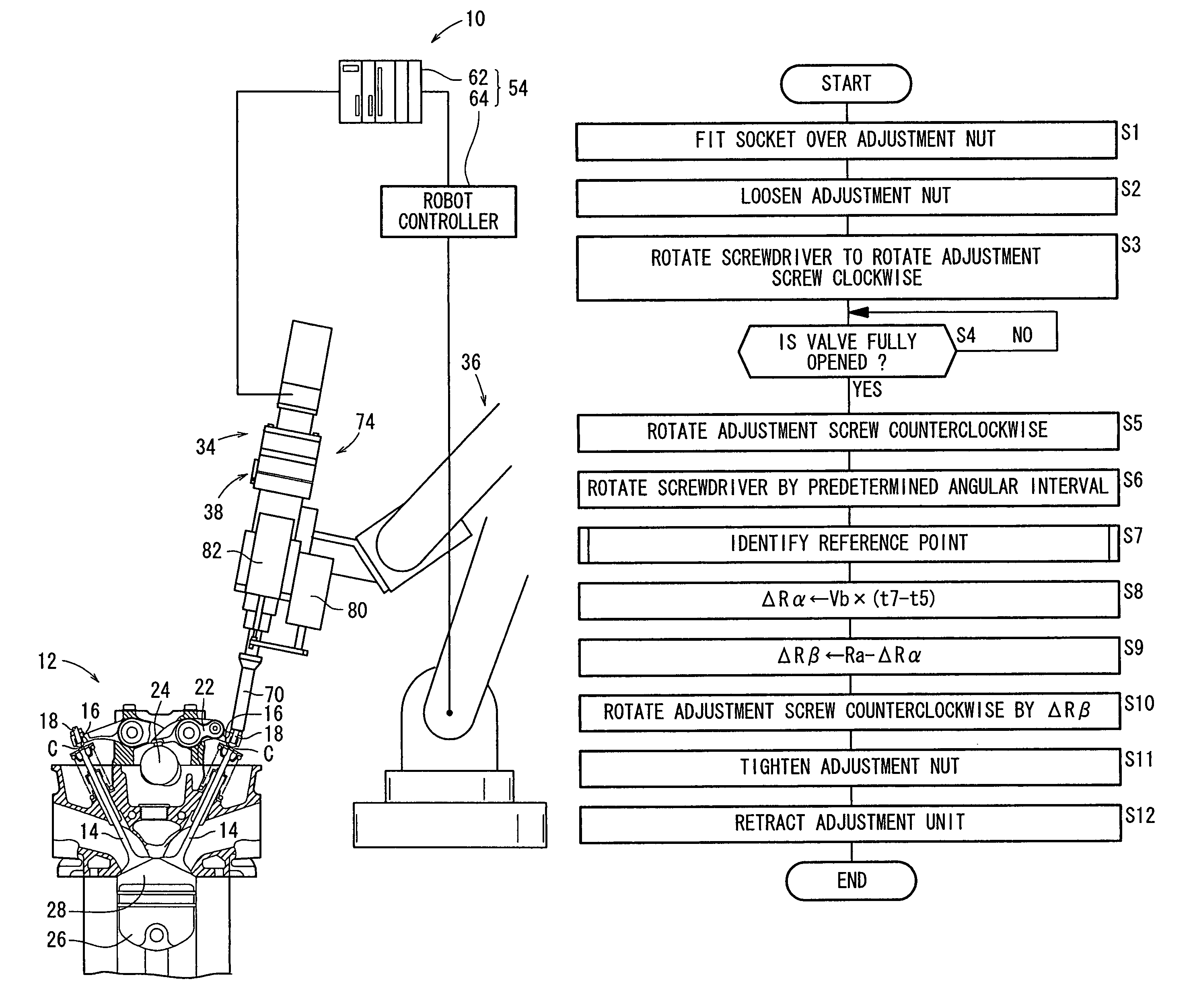
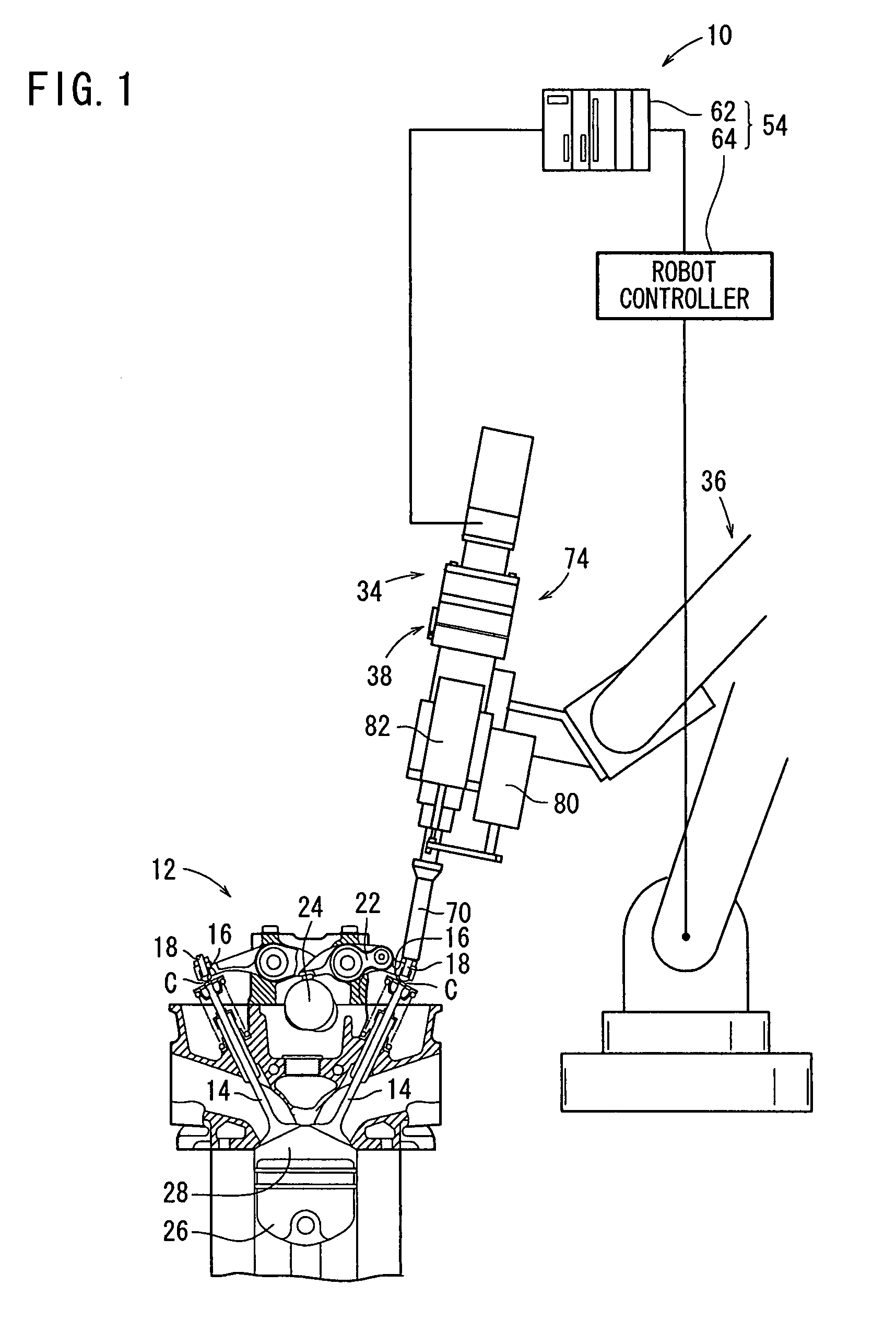
[0035]As shown in FIG. 1, an automatic tappet clearance adjusting apparatus 10 according to an embodiment of the present invention operates to adjust a clearance (hereinafter referred to as a tappet clearance) C between a valve end 16 of a valve 14 of an engine 12 and an adjustment screw 18. The adjustment screw 18 is a fine right-handed screw, which is advanced downwardly when rotated clockwise.

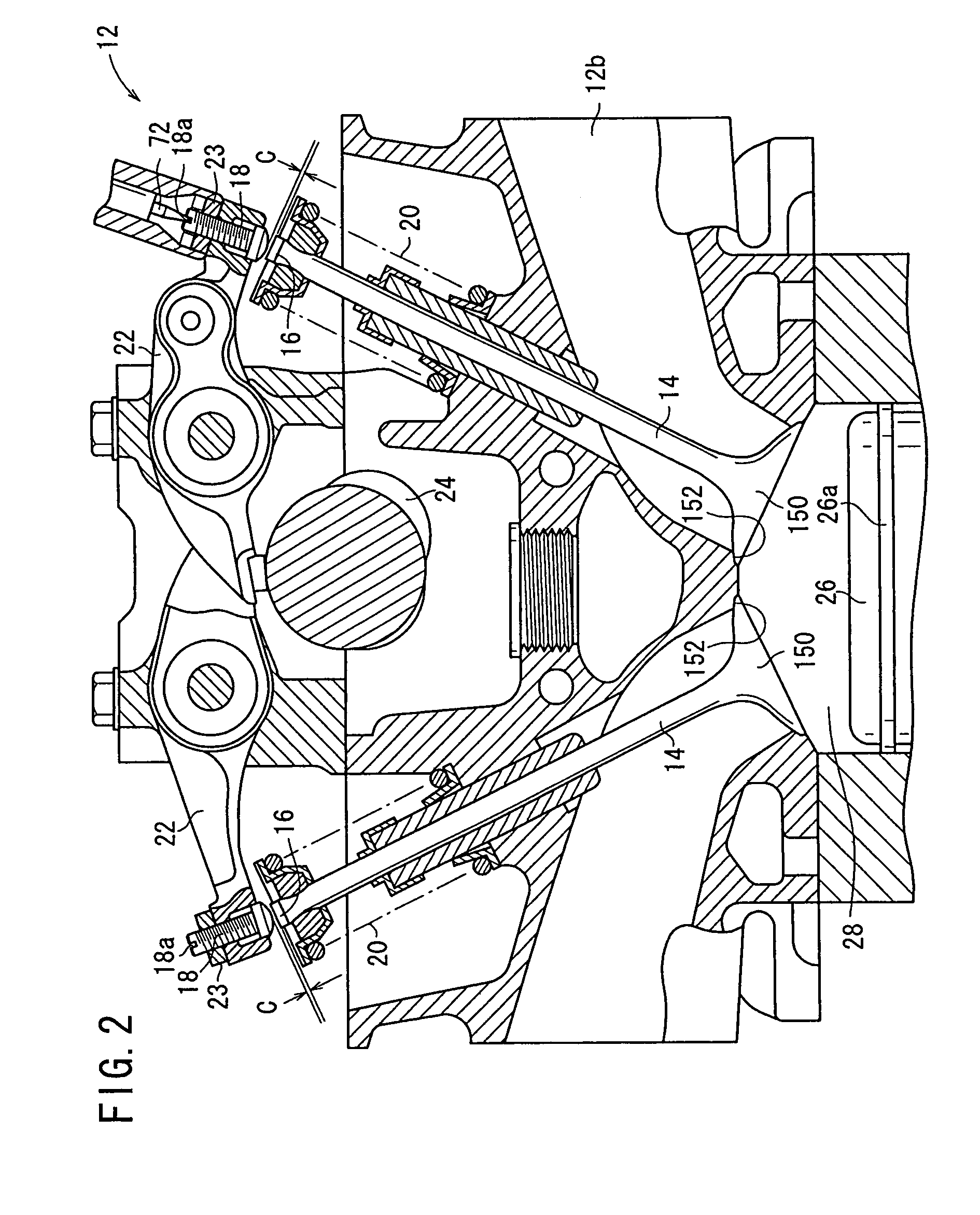
[0036]As shown in FIG. 2, the adjustment screw 18 has a screw section having a straight slot 18a defined in an upper end thereof, the screw section being threaded in the distal end of a rocker arm 22. The adjustment screw 18 is fixed in place by an adjustment nut 23, by means of a double-nut configuration. The engine 12 is of a type wherein the valve end 16 of the valve ...


PUM


Abstract

An automatic tappet clearance adjuster comprising a unit for adjusting the projection by advancing / retracting an adjust screw from the forward end of a rocker arm, a section for detecting the torque by rotating the adjust screw, and a control mechanism section for controlling the adjusting unit according to the torque value measured by the torque detecting section. The control mechanism section measures the torque value continuously when a valve is closed by retracting the adjust screw from the open state of the valve. A rotation reference position corresponding to the intersection of a first approximation line and a second approximation line approximating the sections immediately before and after the inflection point of differential value of the torque value is detected as a reference point, and the adjust screw is retracted by a set amount from the reference point.

Description

CROSS-REFERENCE TO RELATED APPLICATIONS[0001]The present application is a U.S. National phase of, and claims priority based on PCT / JP2005 / 017896, filed 28 Sep. 2005, which, in turn, claims priority from Japanese patent application 2004-283089, filed 29 Sep. 2004. The entire disclosure of each of the referenced priority documents is incorporated herein by reference.BACKGROUND ART[0002]Engines of the type in which a rocker arm is provided in a valve mechanism draw in and discharge a fuel gas and an exhaust gas by pressing a valve end, so as to open the valve with an adjustment screw on the distal end of a rocker arm that is actuated by a cam. When the rocker arm returns to an original position, the valve is closed again under a resilient force of a spring.[0003]A clearance (hereinafter referred to as a tappet clearance) is provided between the valve end and the adjustment screw, for allowing the valve to be fully closed when the rocker arm returns to the original position. If the tapp...

Claims


Application Information

Patent Timeline
Patent Type & Authority Patents(United States)
IPC IPC(8): F01L1/14
CPCF01L1/20F01L1/08F01L1/181F01L2103/01F01L2001/0535F01L2303/01F01L1/46
Inventor TACHINO, YASUYUKIMIYAJIMA, TOSHIYUKITSUYOSHI, TOMOAKI
Owner HONDA MOTOR CO LTD
Why Eureka
Try Eureka