Construction layout tool with line guide

a construction layout and guide technology, applied in the field of hand tools, can solve the problems of inability to accurately read orientation markings and difficulty for users to read orientation markings on the layout tool from a distance, and achieve the effects of convenient alignment, convenient and accurate layout of construction materials, and facilitate alignmen

Inactive Publication Date: 2011-03-17
CERWIN CHAD WILLIAM
View PDF11 Cites 8 Cited by
  • Summary
  • Abstract
  • Description
  • Claims
  • Application Information

AI Technical Summary

Benefits of technology

[0012]In accordance with another aspect of the present invention, a method is provided for use in marking a layout on a piece of construction material. The method involves providing a hand tool, such as described above, for use in marking a layout on a piece of construction material; securing the tool to the piece of construction material; attaching a layout line to the tool; using indicia of the layout tool to extend the layout line in a desired orientation in relation to the piece of construction material and using the layout line to make at least one mark on the piece of construction material. As noted above, a chalk line guide may be used so that the chalk line need not be directly aligned with the markings. Rather, the chalk line guide can be aligned with the markings and then the chalk line guide can be used to position the chalk line. The tool may be positioned in relation to the construction material suc

Problems solved by technology

However, one difficulty associated with operation by a single user is that it may be difficult for that user to read orientation markings on the layout tool from a distance.
In cases where it is desired to execute the

Method used


Image

  • Construction layout tool with line guide
  • Construction layout tool with line guide
  • Construction layout tool with line guide

Examples


Embodiment Construction

[0020]In the following description, the invention is set forth in the context of specific embodiments of a construction layout tool. While specific embodiments are described in detail for purposes of illustration, those skilled in the art will readily appreciate that additional implementations are possible in accordance with the present invention. Accordingly, the following description should be understood as illustrating the principles of the invention and not by way of limitation.

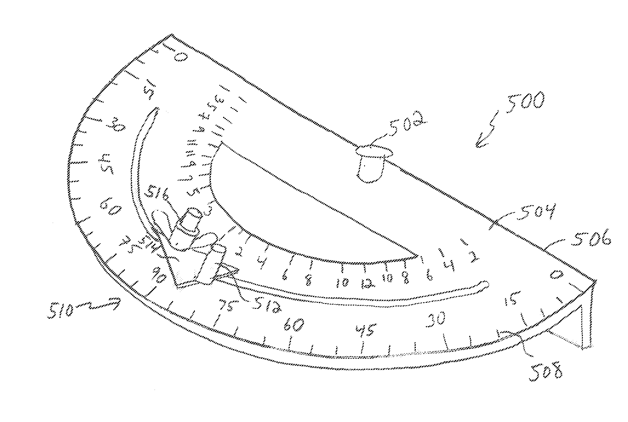
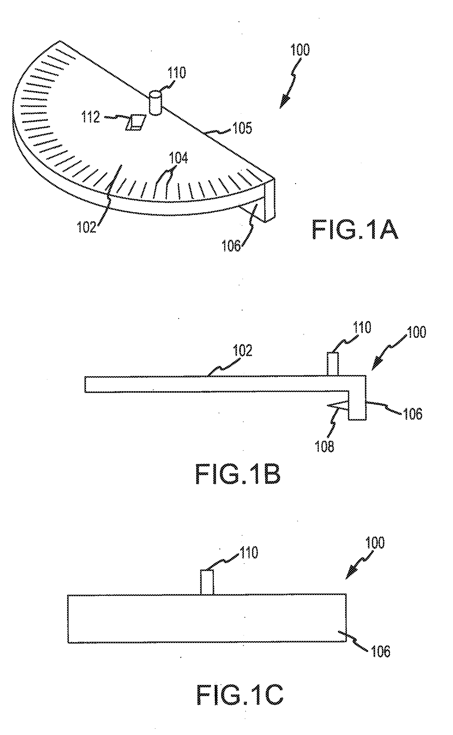
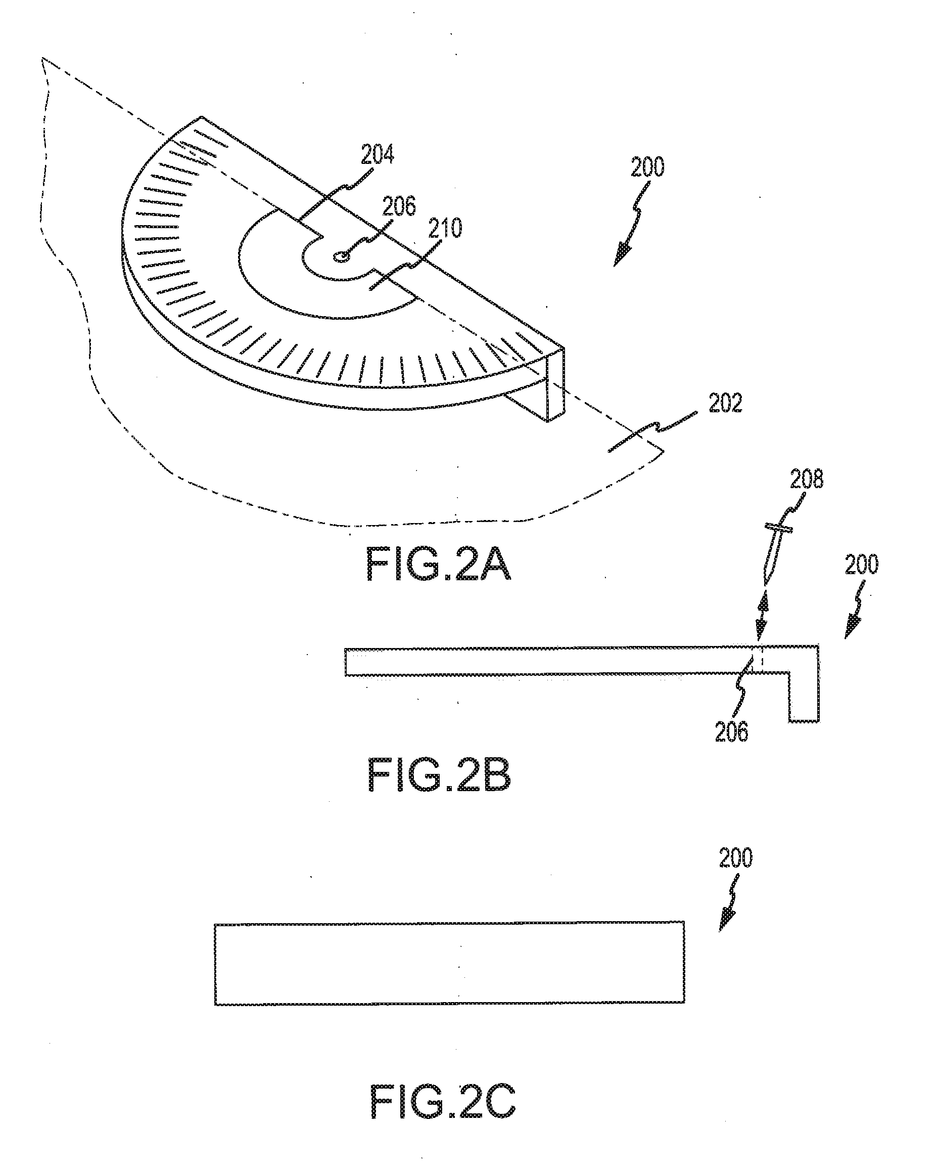
[0021]Referring to FIGS. 1A-1C, a construction tool 100 in accordance with the present invention is shown. The illustrated constriction tool 100 generally includes a top plate 102 and a depending plate 106. The tool 100 may be constructed of any appropriate materials such as plastic, aluminum or other metals or other materials. Moreover, although the illustrated top plate 102 and depending plate 106 are shown as being constructed from an integral web of material, the plates 102 and 106 may be formed in mu...


PUM


Abstract

A layout tool is provided for anchoring a layout line, such as a chalk line, in relation to a piece of construction material. The tool (100) generally includes a top plate (102) and a depending plate (106). Angular markings (104) are provided on the top plate (102) to indicate angles, pitches, or the like. The tool (100) further includes an anchor post (110), a spike (108), and a window or opening (112). A construction worker can align the tool (100) with a mark on the construction material by viewing the mark through the opening (112). The worker can strike the plate (106) so that the spike (108) penetrates a side surface of the construction material to secure the tool (100) in the desired position. A chalk line can then be attached to the post (110) and extended a desired length across the construction material in a desired angular orientation by using the markings (104). The chalk line can then be snapped against the construction material to provide a desired layout chalk line.

Description

CROSS-REFERENCE TO RELATED APPLICATION[0001]This application is a continuation-in-part of U.S. patent application Ser. No. 12 / 428,251, entitled, “CONSTRUCTION LAYOUT TOOL,” filed on Apr. 22, 2009, which claims priority from U.S. Provisional Application No. 61 / 047,042, entitled, “CONSTRUCTION LAYOUT TOOL,” filed on Apr. 22, 2008, the contents of both which are incorporated herein as if set forth in full.FIELD OF THE INVENTION[0002]The invention is related to the field of hand tools for use in construction projects, and in particular, to a tool for marking a layout on a piece of construction material and associated methodology for using the tool.BACKGROUND OF THE INVENTION[0003]In construction projects, it is often necessary to make layout lines or markings on a piece of construction material such as a sheet of plywood, foam material sheet, or oriented strand board (OSB). For example, the layout lines may be used in a subsequent process to cut the construction material or to orient ot...

Claims


Application Information

Patent Timeline
IPC IPC(8): B44D3/38G01B5/24
CPCB25H7/02B43L12/00E04F21/20B43L13/00B43L13/002B43L12/02
Inventor CERWIN, CHAD WILLIAM
Owner CERWIN CHAD WILLIAM
Why Eureka
Try Eureka