Earthquake proof picture hanging system

a picture hanging and earthquake-proof technology, applied in the field of picture hanging systems, can solve the problems of not being able to hang a picture in a very secure way, affecting the quality of the picture, and being subject to failure,

Inactive Publication Date: 2009-07-07
FARRIS LOUIS S
View PDF6 Cites 1 Cited by
  • Summary
  • Abstract
  • Description
  • Claims
  • Application Information

AI Technical Summary

Benefits of technology

[0010]While useful, these devices all require complex clips, and fittings that must be attached to a wall to secure the picture. None are specifically designed to secure a picture in an earthquake.

Problems solved by technology

While easy and fast, it is not a very secure way to hang a picture.
While much more secure, it is subject to failure if the nail or hook is not properly fastened to a wall.
Even a well-hung piece of art, hung using conventional means, can be damaged by a strong earthquake.
Although this device is useful, it requires modification to the wall to accommodate the springs.
Although useful, the elements that are visible above the frame distract from the picture.
While useful, these devices all require complex clips, and fittings that must be attached to a wall to secure the picture.
None are specifically designed to secure a picture in an earthquake.

Method used


Image

  • Earthquake proof picture hanging system
  • Earthquake proof picture hanging system
  • Earthquake proof picture hanging system

Examples


first embodiment

[0041]Note that the structure of the different sized clips is very similar, the main difference being that of size. The manufacturing techniques and materials are the same for all sizes of the

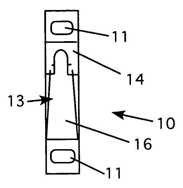
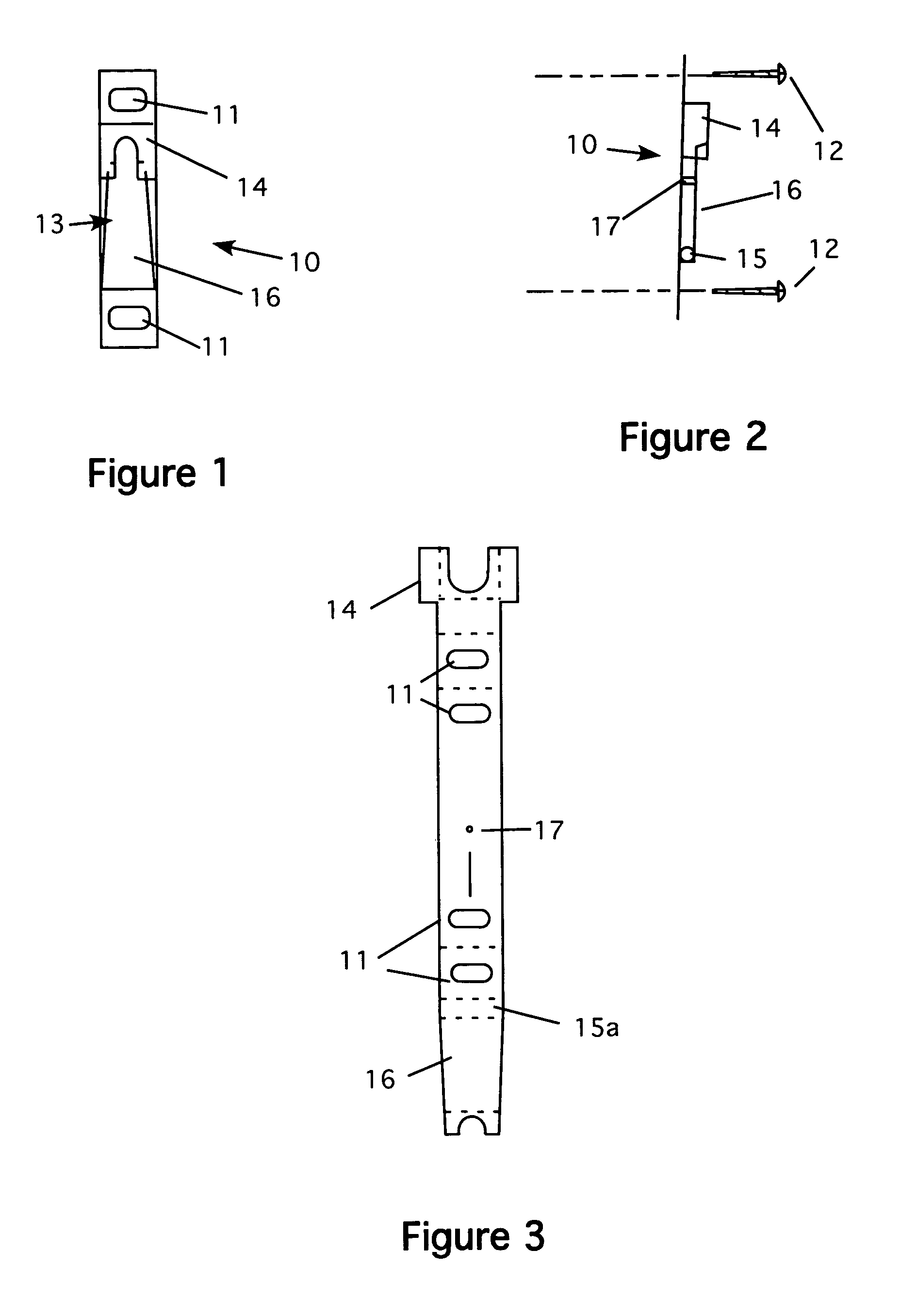
[0042]Referring now to FIG. 1, a front view of the invention used for small frames is shown. This figure shows the clip that is mounted to the back of a frame (see FIG. 10). The clip 10 has two holes 11 for fasteners, such as screws or nails 12 that secure the clip to the frame. The clip also has a spring body 13, which is best shown in FIG. 2. FIG. 2 is a side view of the invention used for small frames. In this view, the spring body 13 is shown, as well as the fasteners 12. The spring body has the following features. At the top of the clip is a retainer box 14. At the bottom of the clip is a coil spring 15, which has a front plate 16 attached. The front plate extends up to fit inside the retainer box 14 as shown. In this way, the coil spring provides a force that pushes the front plate forwar...

second embodiment

[0052]FIG. 15 is a front view of the invention used for large frames. This embodiment is slightly different in that it has four mounting holes to secure it to a frame. This embodiment also needs a considerable frame that has a large outer perimeter to allow the fasteners holding the clips to get a good purchase in the frame. In this embodiment, the clip 60 is formed as shown. This clip 60 has four holes 61 for fasteners, such as screws or nails 62 that secure the clip to the frame. The clip also has a spring body 63, which is best shown in FIG. 16. Here, the spring body 63 is shown, as well as the fasteners 62. The spring body has the following features. At the top of the clip is a retainer box 64. At the bottom of the clip is a coil spring 65, which has a front plate 66 attached. The front plate extends up to fit inside the retainer box 64 as shown. In this way, the coil spring provides a force that pushes the front plate forward against the front of the retainer box. A second spri...


PUM


Abstract

The instant invention uses spring-loaded clips that mount to the back of a frame. The picture is then hung on a wall by slipping these clips over hooks or nails secured to a wall. The hooks are secured in the spring-loaded clips and cannot be removed without a special tool. The clips are made in several sizes to support small, medium, large and very large frames. The clips are made from punched metal that is folded into the clip form. A small spring is secured to the clip to ensure smooth action of the clips in use and to provide a tight, secure fit when the picture is hung.

Description

CROSS REFERENCE TO RELATED APPLICATIONS[0001]Not ApplicableSTATEMENT REGARDING FEDERALLY SPONSORED RESEARCH AND DEVELOPMENT[0002]Not ApplicableBACKGROUND OF THE INVENTION[0003]1. Field of the Invention[0004]This invention relates to picture hanging systems and particularly to picture hanging systems that are earthquake proof.[0005]2. Description of the Prior Art[0006]Picture hanging is a technique that goes back centuries. Today, there are a few different systems for hanging pictures, photographs and other framed art works. The simplest is to hang the frame on a nail driven into a wall. While easy and fast, it is not a very secure way to hang a picture. Another common way to hang a picture is to attach a length of wire to the back of the frame and to hang the wire on a nail or hook. While much more secure, it is subject to failure if the nail or hook is not properly fastened to a wall.[0007]A special consideration involves hanging pictures in earthquake prone areas. A mild earthquak...

Claims


Application Information

Patent Timeline
Patent Type & Authority Patents(United States)
IPC IPC(8): B60R1/02
CPCA47G1/162A47G2001/207
Inventor FARRIS, LOUIS S.
Owner FARRIS LOUIS S
Why Eureka
Try Eureka